This topic shows a simple example for interfacing LCD display (with HD44780 or compliant controller) with PIC16F877A microcontroller using CCS PIC C compiler.
In 4-bit mode there are 7 data lines between the PIC microcontroller and the LCD which are: RS, R/W, E, D4, D5, D6 and D7.
Hardware Required:
- PIC16F877A microcontroller —> datasheet
- 1602 LCD display
- 8 MHz crystal oscillator
- 2 x 22 pF ceramic capacitor
- 10k Ohm resistor
- 10k Ohm variable resistor (or potentiometer)
- PIC microcontroller programmer (PICkit 3, PICkit 4 …)
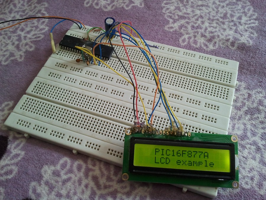
Interface PIC16F877A with LCD circuit:
PIC16F877A LCD example circuit schematic diagram is shown below.
 As the PIC16F877A microcontroller has no internal oscillator circuit, a crystal oscillator with 8MHz is used as a clock source for the microcontroller. The MCLR pin of the microcontroller is connected to +5V through 10k Ohm resistor.
The microcontroller is supplied with 5 Volts where the positive terminal of the power source is connected to VDD pins (#11 & #32) and the negative terminal is connected to VSS pins (#12 & #32), power pins are not shown in the circuit diagram.
The LCD used in this example has 2 lines and 16 columns, its connection is as described below:
VDD & VSS pins are power supply pins of the LCD module where VDD is connected to positive terminal of the power supply and VSS is connected to negative terminal.
VEE Pin (also known as V0) of the LCD module is connected to a 10k Ohm variable resistor output. The usage of the variable resistor allows us to easily control the contrast of the LCD display.
RS (Register Select) Pin is connected to pin RC0 of PIC16F877A microcontroller.
RW (Read/Write) Pin is connected to pin RC1.
E (Enable) Pin of the LCD is connected to pin RC2 of the PIC16F877A MCU.
Data pins, D4, D5, D6, & D7 are respectively connected to MCU pins RC3, RC4, RC5, & RC6.
A and K pins of the LCD are backlight LED anode and cathode terminal, they are respectively connected to GND and +5V (not shown in circuit diagram).
Pins D0, D1, D2, & D3 are not connected pins because 4-bit mode is used, alternatively, they can be connected to ground.
Interface PIC16F877A with LCD display C code:
The C code below was tested with CCS C compiler version 5.051.
1 2 3 4 5 6 7 8 9 10 11 12 13 14 15 16 17 18 19 20 21 22 23 24 25 26 27 28 29 30 31 32 33 34 35 36 37 38 39 40 41 42 | // Interfacing PIC16F877A with LCD display CCS C code // https://simple-circuit.com/ //LCD module connections #define LCD_RS_PIN PIN_C0 #define LCD_RW_PIN PIN_C1 #define LCD_ENABLE_PIN PIN_C2 #define LCD_DATA4 PIN_C3 #define LCD_DATA5 PIN_C4 #define LCD_DATA6 PIN_C5 #define LCD_DATA7 PIN_C6 //End LCD module connections #include <16F877A.h> #use delay(crystal=8000000) #include <lcd.c> char i; void main(){ lcd_init(); // Initialize LCD module while(TRUE){ lcd_putc('f'); lcd_gotoxy(4, 1); // Go to column 4 row 1 lcd_putc("PIC16F877A"); lcd_gotoxy(4, 2); // Go to column 4 row 2 lcd_putc("LCD example"); delay_ms(5000); lcd_putc('f'); // LCD clear lcd_gotoxy(3, 1); // Go to column 3 row 1 lcd_putc("Hello world!"); lcd_gotoxy(2, 2); // Go to column 2 row 2 lcd_putc("Have a nice day"); delay_ms(5000); lcd_putc('f'); // LCD clear lcd_gotoxy(3, 1); // Go to column 3 row 1 lcd_putc("Hello world!"); for(i = 0; i < 200; i++){ lcd_gotoxy(7, 2); // Go to column 7 row 2 printf(lcd_putc,"%3u",i); // Write i with 3 numbers max delay_ms(100);} } } |
Interface PIC16F877A with LCD video: