PIC16F877A PWM ADC Example
The microcontroller PIC16F877A has two CCP modules and with these modules we can generate two PWM (Pulse Width Modulation) signals PWM1 related with CCP1 and PWM2 related with CCP2. Both PWM modules use Timer2 to generate signals which means the two modules will have the same frequency.
This topic shows how to use PIC16F877A PWM modules using CCS PIC C compiler.
First we have to configure the CCP module to run as a PWM using the following CCS commands:
setup_ccp1(CCP_PWM); // Configure CCP1 as a PWM
setup_ccp2(CCP_PWM); // Configure CCP2 as a PWM
Then we have to use Timer2 to setup the pwm frequency.
Use the following equation to compute the pwm frequency:
PWM period = [(PR2) + 1] • 4 • Tosc • (TMR2 Prescale Value)
Where PWM frequency is defined as 1/[PWM period].
PR2 is Timer2 preload value,
Tosc = 1/(MCU_frequency)
TMR2 Prescale Value can be 1, 4 or 16.
For example for PR2 = 255 , microcontroller frequency = 8MHz and Prescale = 16 we get a PWM frequency of 488Hz.
The CCS Timer2 configuration has the following form:
setup_timer_2(mode, period, postscale);
where: mode is TMR2 Prescale Value, period is PR2 and postscaler is not used in the determination of the PWM frequency (keep it 1).
Previous example gives the following Timer2 configuration command:
setup_timer_2(T2_DIV_BY_16, 255, 1);
The last CCS command is the PWM duty cycle command:
set_pwm1_duty(value);
PIC16F877A ADC + PWM example:
This example shows how to use the digital value of the analog reading to set the duty cycle of the PWM signal. This example uses two analog channels AN0 and AN1 and the two CCP modules CCP1 andCCP2 to control the brightness of two LEDs connected to RC2 (CCP1 output) and RC1 (CCP2 output) as shown in the following circuit schematic:
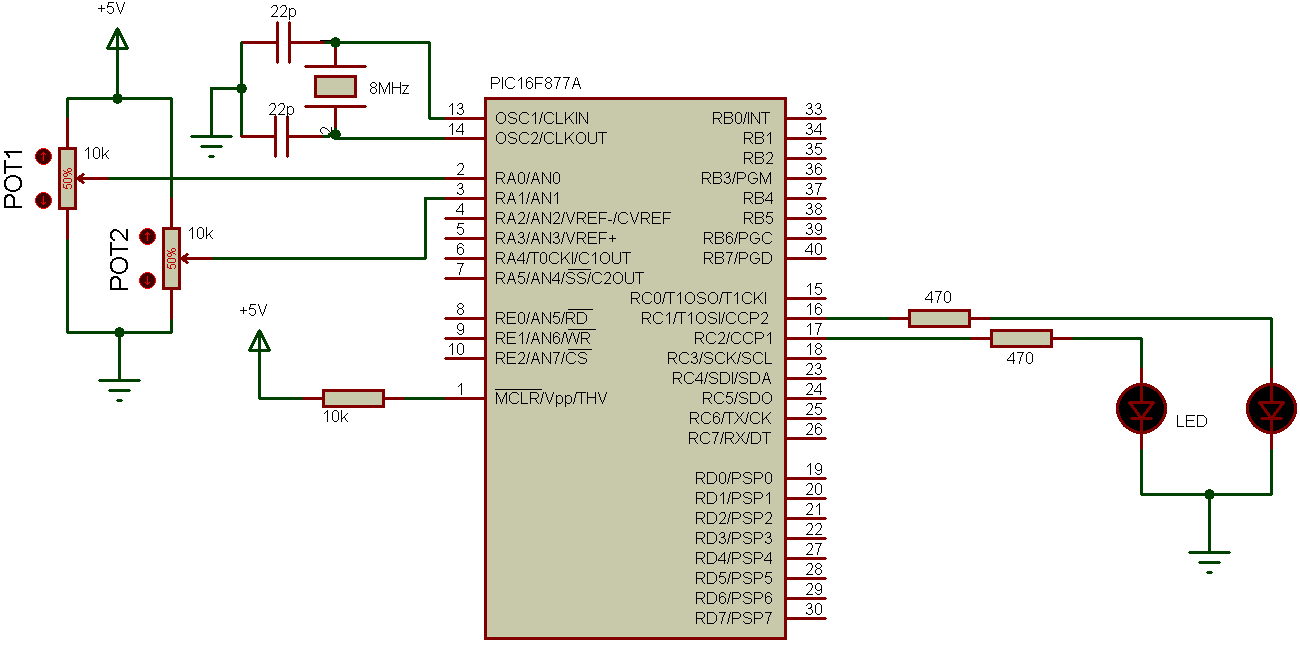
Two pots are used to control the brightness of the LEDs. The microcontroller PIC16F877A runs with 8MHz crystal oscillator. If the frequency of the oscillator changed, the PWM frequency will also change.
To see how to use PIC16F877A ADC module see the following topic:
PIC16F877A ADC example with CCS PIC C compiler
Hardware Required:
- PIC16F877A microcontroller —> datasheet
- 2 x LED
- 2 x 10k Ohm potentiometer
- 10k Ohm resistor
- 8 MHz crystal oscillator
- 2 x 22pF capacitor
- Bread board and jumper wires
- PIC microcontroller programmer (PICkit 2, PICkit 3…)
PIC16F877A ADC + PWM example C code:
The following C code was tested with CCS C compiler version 5.051.
1 2 3 4 5 6 7 8 9 10 11 12 13 14 15 16 17 18 19 20 21 22 23 24 25 26 27 28 29 | // PIC16F877A PWM + ADC example with CCS C compiler // https://simple-circuit.com/ #include <16F877A.h> #fuses HS,NOWDT,NOPROTECT,NOLVP #device ADC=8 // Set ADC resolution to 8-bit #use delay(clock=8000000) unsigned int8 i, j; void main(){ setup_adc(ADC_CLOCK_DIV_32); // Set ADC conversion time to 32Tosc setup_adc_ports(AN0_AN1_AN3); // Configure AN0,AN1 and AN3 as analog setup_ccp1(CCP_PWM); // Configure CCP1 as a PWM setup_ccp2(CCP_PWM); // Configure CCP2 as a PWM delay_ms(100); // Wait 100ms setup_timer_2(T2_DIV_BY_16, 255, 1); // Set PWM frequency to 488Hz while(TRUE){ set_adc_channel(0); // Select channel AN0 delay_ms(1); // Wait 1ms i = read_adc(); // Read from AN0 and store in i delay_ms(1); // Wait 1ms set_adc_channel(1); // Select channel AN1 delay_ms(1); // Wait 1ms j = read_adc(); // Read from AN1 and store in j set_pwm1_duty(i); set_pwm2_duty(j); delay_ms(1); // Wait 1ms } } |
In this example the PWM resolution is 8-bit, if you want to use 10-bit pwm resolution change ADC resolution from 8 to 10 and declare i, j as int16 variables.
PIC16F877A ADC + PWM video:
The following video shows a real hardware circuit of the previous example.

Hey I tried to run on mplab..I couldn’t run the code..can u help me