This topic shows how to connect PIC16F877A microcontroller with SSD1306 OLED display and DS18B20 temperature sensor. The DS18B20 sensor provides 9-bit to 12-bit Celsius temperature measurement resolution (programmable resolution). The default resolution is 12-bit which is used in this project.
The SSD1306 OLED used in this project is configured to work in I2C mode, some SSD1306 OLED boards may require a small hardware modifications (to select between SPI mode or I2C mode) such as soldering, placing jumpers …
Related Projects:
The following topics may contain some useful information about the current project.
Interfacing PIC16F877A with SSD1306 OLED display
Interfacing PIC16F877A with DS18B20 temperature sensor
Hardware Required:
- PIC16F877A microcontroller
- SSD1306 OLED display (128×64 Pixel)
- DS18B20 temperature sensor
- 8 MHz crystal oscillator
- 2 x 22pF ceramic capacitor
- 10k ohm resistor
- 4.7k ohm resistor
- 5V power source
- Breadboard
- Jumper wires
PIC16F877A with SSD1306 and DS18B20 circuit:
Project circuit schematic diagram is shown below.
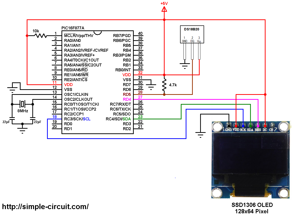
(All grounded terminal are connected together)
The PIC16F877A microcontroller has one hardware I2C module with SDA on pin RC4 (#23) and SCL on pin RC3 (#18). The SDA pin of the MCU is connected to the SDA pin of the display and the SCL pin of the MCU is connected to the SCL pin of the display.
The reset pin of the display is connected to pin RD4 (#27) of the microcontroller.
The SSD1306 OLED display DC pin is connected to VDD which means the I2C slave address of the display is 0x7A.
The DS18B20 temperature sensor has 3 pins: VCC (+5V), data and GND. The data pin is connected to PIC16F877A pin RD5 (#28).
PIC16F877A with SSD1306 and DS18B20 code:
The C code below is for CCS C compiler, it was tested with version 5.051.
To be able to compile the C code below with no error, a driver for the SSD1306 OLED display is required, it’s name is SSD1306.C, its download link is below:
SSD1306 OLED display driver
after the download, add the driver file to the project folder or CCS C compiler drivers folder.
Functions used in the code:
int1 ds18b20_start(): used to know if the DS18B20 sensor is correctly connected to the circuit, returns TRUE (1) if OK and FALSE (0) if error.
void ds18b20_write_bit(int1 value): writes (sends) 1 bit to the DS18B20 sensor, the bit is ‘value’ which may be 1 or 0.
void ds18b20_write_byte(int8 value): writes 1 byte (8 bits) to the DS18B20 sensor, this function is based on the previous function. This function writes LSB (Least Significant Bit) first.
int1 ds18b20_read_bit(void): reads 1 bit from the DS18B20 sensor, returns the read value (1 or 0).
int8 ds18b20_read_byte(void): reads 1 byte (8 bits) from the DS18B20 sensor, this function is based on the previous function. This function reads LSB first.
int1 ds18b20_read(int16 *raw_temp_value): reads the temperature raw data which is 16-bit long (two 8-bit registers), the data is stored in the variable raw_temp_value, returns TRUE if OK and FALSE if error.
The value of the temperature in degree Celsius is equal to the raw value divided by 16 (in case of 12-bit resolution). The default resolution of the DS18B20 is 12 bits.
Rest of code is described through comments.
1 2 3 4 5 6 7 8 9 10 11 12 13 14 15 16 17 18 19 20 21 22 23 24 25 26 27 28 29 30 31 32 33 34 35 36 37 38 39 40 41 42 43 44 45 46 47 48 49 50 51 52 53 54 55 56 57 58 59 60 61 62 63 64 65 66 67 68 69 70 71 72 73 74 75 76 77 78 79 80 81 82 83 84 85 86 87 88 89 90 91 92 93 94 95 96 97 98 99 100 101 102 103 104 105 106 107 108 109 110 111 112 113 114 115 116 117 118 119 120 121 122 123 124 125 126 127 128 129 130 131 132 133 134 135 136 137 138 139 140 141 142 143 144 145 146 147 148 149 150 151 152 153 154 155 156 | /************************************************************************************** PIC16F877A microcontroller with SSD1306 OLED (128x64 Pixel) and DS18B20 temperature sensor C Code for CCS C compiler Crystal oscillator used @ 8MHz This is a free software with NO WARRANTY. http://simple-circuit.com/ ***************************************************************************************/ // SSD1306 OLED reset pin definition #define SSD1306_RST PIN_D4 // DS18B20 Data pin is connected to pin RD5 #define DS18B20_PIN PIN_D5 #include <16F877A.h> #fuses HS, NOWDT, NOPROTECT, NOLVP #use delay(clock = 8MHz) #use fast_io(B) #use I2C(MASTER, I2C1, FAST = 400000, stream = SSD1306_STREAM) // initialize I2C // include SSD1306 OLED driver source code #include <SSD1306.c> // Variables declaration int16 raw_temp; char *temp = "000.0000 C"; char degree[] = {0, 7, 5, 7, 0}; // degree symbol custom char int1 ds18b20_start(){ output_low(DS18B20_PIN); // Send reset pulse to the DS18B20 sensor output_drive(DS18B20_PIN); // Configure DS18B20_PIN pin as output delay_us(500); // Wait 500 us output_float(DS18B20_PIN); // Configure DS18B20_PIN pin as input delay_us(100); //wait to read the DS18B20 sensor response if (!input(DS18B20_PIN)) { delay_us(400); // Wait 400 us return TRUE; // DS18B20 sensor is present } return FALSE; } void ds18b20_write_bit(int1 value){ output_low(DS18B20_PIN); output_drive(DS18B20_PIN); // Configure DS18B20_PIN pin as output delay_us(2); // Wait 2 us output_bit(DS18B20_PIN, value); delay_us(80); // Wait 80 us output_float(DS18B20_PIN); // Configure DS18B20_PIN pin as input delay_us(2); // Wait 2 us } void ds18b20_write_byte(int8 value){ int8 i; for(i = 0; i < 8; i++) ds18b20_write_bit(bit_test(value, i)); } int1 ds18b20_read_bit(void) { int1 value; output_low(DS18B20_PIN); output_drive(DS18B20_PIN); // Configure DS18B20_PIN pin as output delay_us(2); output_float(DS18B20_PIN); // Configure DS18B20_PIN pin as input delay_us(5); // Wait 5 us value = input(DS18B20_PIN); delay_us(100); // Wait 100 us return value; } int8 ds18b20_read_byte(void) { int8 i, value = 0; for(i = 0; i < 8; i++) shift_right(&value, 1, ds18b20_read_bit()); return value; } int1 ds18b20_read(int16 *raw_temp_value) { if (!ds18b20_start()) // Send start pulse return FALSE; ds18b20_write_byte(0xCC); // Send skip ROM command ds18b20_write_byte(0x44); // Send start conversion command while(ds18b20_read_byte() == 0); // Wait for conversion complete if (!ds18b20_start()) // Send start pulse return FALSE; // Return 0 if error ds18b20_write_byte(0xCC); // Send skip ROM command ds18b20_write_byte(0xBE); // Send read command *raw_temp_value = ds18b20_read_byte(); // Read temperature LSB byte and store it on raw_temp_value LSB byte *raw_temp_value |= (int16)(ds18b20_read_byte()) << 8; // Read temperature MSB byte and store it on raw_temp_value MSB byte return TRUE; // OK --> return 1 } // main function void main(void) { delay_ms(1000); // Initialize the SSD1306 OLED with an I2C addr = 0x7A (default address) SSD1306_Init(SSD1306_SWITCHCAPVCC, SSD1306_I2C_ADDRESS); // clear the whole display SSD1306_ClearDisplay(); SSD1306_GotoXY(5, 2); SSD1306_PutC("DS18B20 SENSOR"); SSD1306_GotoXY(6, 5); SSD1306_PutC("TEMPERATURE:"); while (TRUE) { if(ds18b20_read(&raw_temp)) { if(raw_temp & 0x8000) { // If the temperature is negative temp[0] = '-'; // Put minus sign (-) raw_temp = ~raw_temp + 1; // Change temperature value to positive form } else { if((raw_temp >> 4) >= 100) // If the temperatue >= 100 °C temp[0] = '1'; // Put 1 of hundreds else // otherwise temp[0] = ' '; // put space ' ' } // Put the first two digits ( for tens and ones) temp[1] = ( (raw_temp >> 4) / 10 ) % 10 + '0'; // Put tens digit temp[2] = (raw_temp >> 4) % 10 + '0'; // Put ones digit // Put the 4 fraction digits (digits after the point) // Why 625: because we're working with 12-bit resolution (default resolution) temp[4] = ( (raw_temp & 0x0F) * 625) / 1000 + '0'; // Put thousands digit temp[5] = (((raw_temp & 0x0F) * 625) / 100 ) % 10 + '0'; // Put hundreds digit temp[6] = (((raw_temp & 0x0F) * 625) / 10 ) % 10 + '0'; // Put tens digit temp[7] = ( (raw_temp & 0x0F) * 625) % 10 + '0'; // Put ones digit SSD1306_GotoXY(6, 7); printf(SSD1306_PutC, temp); SSD1306_GotoXY(14, 7); SSD1306_PutCustomC(degree); // degree symbol ( ° ) } else { SSD1306_GotoXY(6, 7); // Go to column 4 row 2 SSD1306_PutC(" Error! "); } delay_ms(1000); // Wait 1 second } } // End of code. |
PIC16F877A + SSD1306 OLED + DS18B20 sensor Proteus simulation:
Proteus simulation file download link is below, use it with version 8.6 or higher:
PIC16F877A + SSD1306 OLED + DS18B20 sensor
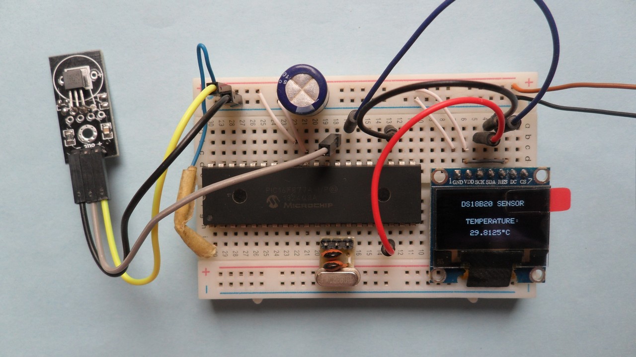
The following video shows my simulation result (simulation circuit is not the same as the hardware circuit, hardware circuit diagram is shown above):