This is an example shows how to write texts on SSD1306 OLED display (128×64 pixel) using PIC16F877A microcontroller. In this project the SSD1306 OLED is configured to work in I2C mode. So, make sure that your SSD1306 OLED display is configured to work in I2C mode, some displays need jumper placing or some soldering.
A small video shows Proteus simulation of this project at the end of the post.
This topic is for interfacing PIC microcontroller devices with limited RAM with SSD1306 OLED display, if the MCU device has sufficient RAM (as an example with more than 1024 byte for 128×64 Pixel display) it is recommended to use the library described in the post below:
SSD1306 OLED Library for CCS C compiler
The SSD1306 OLED display communicates with the master device over I2C mode, SPI mode or 8-bit parallel mode.
Generally the SSD1306 OLED requires a RAM buffer with all screen data, for example if we’ve a 128×64 Pixel display then we’ve to use a buffer of 1024 bytes (128×64/8). The problem is when we want to write a single pixel we’ve to overwrite another 7 pixels, therefore we need to know the status of the other 7 pixels.
Another problem with this type of displays (the SSD1306 controller chip) is it doesn’t allow any reading from its RAM when it works in serial mode (I2C or SPI).
In this example the SSD1306 works in I2C mode and the PIC16F877A has a limited RAM of 368 bytes which means using a buffer of 1024 byte is not possible.
I wrote a small driver for the SSD1306 OLED in order to be able to write texts, this driver works with SSD1306 displays with resolution of 128×64, 128×32 and 96×16 pixel, it splits the 128×64 pixel display into 21 columns and 8 rows, the 128×32 pixel into 21 columns and 4 rows, the 96×16 pixel into 16 columns and 2 rows. So in a display of 128×64 pixel we can write up to 168 character (21×8). The driver has a built-in font of 5×7.
SSD1306 OLED display driver functions:
This is a list of all user functions of the driver.
SSD1306_Init(vccstate, i2caddr); initializes the display, i2caddr is the display address.
SSD1306_StartScrollRight(start, stop); scroll right
SSD1306_StartScrollLeft(start, stop); scroll left
SSD1306_StartScrollDiagRight(start, stop); scroll diagonal right
SSD1306_StartScrollDiagLeft(start, stop); scroll diagonal left
SSD1306_StopScroll(); stop scrolling
SSD1306_ClearDisplay(); clears the display.
SSD1306_FillScreen(); fills the whole screen.
SSD1306_Dim(dim); dim the display, dim can be 1 (true) or 0 (false).
SSD1306_InvertDisplay(i); inverts the display, i can be 1 or 0.
SSD1306_GotoXY(x, y); move cursor to position (x, y).
SSD1306_PutC(c); draws a character c on the screen position (x, y).
SSD1306_PutCustomC(char *c); draws a custom character c on the screen. c dimension should be 5×7.
The library supports 3 types of the SSD1306 OLED display depending on the screen resolution, these types are: 128×64 pixel, 128×32 pixel and 96×16 pixel. The default type is: 128×64 pixel.
If you want to use it with the 128×32 pixel type just define it in the main code as:
#define SSD1306_128_32
and if the 96×16 pixel type is used, the definition becomes:
#define SSD1306_96_16
Note that the library doesn’t support defining both previous types at once and compiling a code with the two definitions (#define SSD1306_128_32 and #define SSD1306_96_16) will give an error.
Interfacing PIC16F877A with SSD1306 OLED display:
Hardware Required:
- PIC16F877A microcontroller
- SSD1306 OLED display
- 20MHz crystal oscillator
- 2 x 22pF ceramic capacitor
- 10k ohm resistor
- 5V source
- Breadboard
- Jumper wires
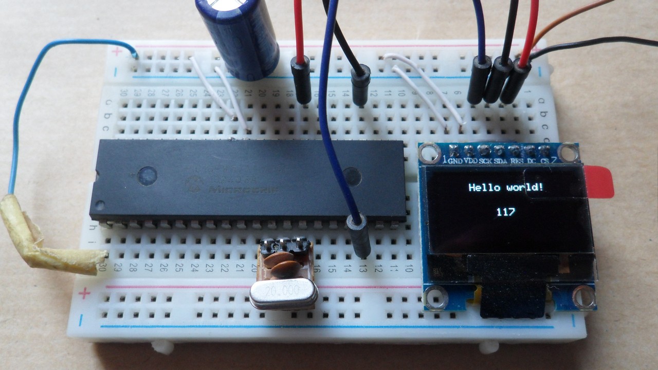
The Circuit:
Project circuit diagram is shown below.

(All grounded terminals are connected together)
The PIC16F877A microcontroller has one hardware I2C module with SDA on pin RC4 (#23) and SCL on pin RC3 (#18). The SDA pin of the MCU is connected to the SDA pin of the display and the SCL pin of the MCU is connected to the SCL pin of the display.
The reset pin of the display is connected to pin RD4 (#27) of the microcontroller.
The SSD1306 OLED display DC pin is connected to VDD which means the I2C slave address of the display is 0x7A.
The Code:
The C code below is for CCS C compiler, it was tested with version 5.051.
To be able to compile the C code below with no error, a driver for the SSD1306 OLED display is required, it’s name is SSD1306.C, its download link is below:
SSD1306 OLED display driver
after the download, add the driver file to project folder or CCS C compiler drivers folder.
CCS C code:
1 2 3 4 5 6 7 8 9 10 11 12 13 14 15 16 17 18 19 20 21 22 23 24 25 26 27 28 29 30 31 32 33 34 35 36 37 38 39 40 41 42 43 44 45 46 47 48 49 50 51 52 53 54 55 56 57 58 59 60 61 62 63 64 65 66 | // Interfacing PIC16F877A with SSD1306 OLED display (128x64 Pixel) // http://simple-circuit.com/ #define SSD1306_RST PIN_D4 #include <16F877A.h> #fuses HS,NOWDT,NOPROTECT,NOLVP #use delay(clock = 20MHz) #use I2C(MASTER, I2C1, FAST = 400000, stream = SSD1306_STREAM) // Initialize I2C // Include SSD1306 OLED driver source code #include <SSD1306.c> int8 i = 0; void main() { delay_ms(500); // Initialize the SSD1306 OLED with an I2C addr = 0x7A (default address) SSD1306_Init(SSD1306_SWITCHCAPVCC, SSD1306_I2C_ADDRESS); // clear the display SSD1306_ClearDisplay(); SSD1306_GotoXY(1, 1); SSD1306_PutC("Interfacing PIC16F877A with SSD1306 OLED display"); delay_ms(5000); SSD1306_ClearDisplay(); SSD1306_GotoXY(6, 2); SSD1306_PutC("Hello world!"); delay_ms(2000); SSD1306_StartScrollRight(1, 1); delay_ms(3000); SSD1306_StopScroll(); SSD1306_StartScrollLeft(1, 1); delay_ms(3000); SSD1306_StopScroll(); SSD1306_StartScrollDiagRight(1, 1); delay_ms(3000); SSD1306_StopScroll(); SSD1306_StartScrollDiagLeft(1, 1); delay_ms(3000); SSD1306_StopScroll(); delay_ms(3000); SSD1306_ClearDisplay(); SSD1306_GotoXY(6, 2); SSD1306_PutC("Hello world!"); delay_ms(2000); while(TRUE) { SSD1306_GotoXY(10, 5); printf(SSD1306_PutC, "%03u", i++); delay_ms(500); } } // End of code |
PIC16F877A + SSD1306 OLED Proteus simulation:
This project can be simulated with Proteus simulation software, but it will not give a prefect result as the real hardware circuit. The simulation file can be downloaded from the link below, use Proteus version 8.6 or higher to open it:
PIC16F877A + SSD1306 OLED
and the video below shows the simulation result:
Other examples with PIC16F877A microcontroller and SSD1306 OLED display:
PIC16F877A with DHT11 sensor and SSD1306 OLED
PIC16F877A with DHT22 (AM2302) sensor and SSD1306 OLED display
Real time clock with PIC16F877A, SSD1306 OLED and DS1307
Temperature monitor with PIC16F877A, SSD1306 and DS18B20 sensor
Interfacing PIC16F877A with SSD1306 OLED and DS3231 RTC

Hello, note: these types of displays are 3.3V I2C bus.
Hello, I want to make an ECG circuit with pic16f877a and SSD1306OLED. Can i display an ECG signal on this?
I am doing this in MPLAB but I couldn’t understand from where do I get the i2c library
*** Error 12 “testing.c” Line 83(15,16): Undefined identifier — SSD1306_Init
Hola, una pregunta, de que depende el FAST=400000? en las instrucciones de la libreria dice que debe trabajarse a 100000 y en varios proyectos usas 400000 y 800000
Muchas gracias por el aporte
400000 means the clock frequency in Hz (400000 = 400kHz). The higher clock frequency the faster data transfer.
The setting of the clock frequency depends of the slave device, you’ve to put a frequency where the slave device is able to work with.
Tengo la misma pregunta, (I have the same question, how can I change the text size?)
With this library the text size is fixed.
This library is designed for microcontrollers with limited RAM like the PIC16F877A which has only 368 bytes.
If you have a microcontroller with more RAM space (for example 2kB) consider using this library which allows
you to change the text size:
PIC18F46K22 with SSD1306 OLED Display – I2C Mode Example
Como le doy tamaño al texto y usaría un pic 18f2550
OLED display shouldn’t work at 3V3? At least the logic part….
The SSD1306 OLED board should have a 3V3 regulator to supply the display with 3V3.
I2C Communication is an open drain/collector which means there are two pull-up resistors that raise the lines to 3.3V (or 5V …). These resistors (10k ohm each) are placed on the SSD1306 board and they are connected to 3V3 line that comes from the regulator.
Hi bro.
Can you sent to me hex file of this project.
When I built your project with ccs5.015 and wrote to pic, It don’t display any thing.
If there was no error while compiling the C code, then it should work. Check the circuit connections!
Hi, I was the same issue, but I solved it changin the SSD1306_I2C_ADDRESS it was 0x7A and I changed by 0x78 and wala it works.
Thanks, it also works for me