This post shows how to control speed and rotation direction of unipolar stepper motor using PIC16F877A microcontroller and CCS PIC C compiler.
Related topic:
Bipolar stepper motor control with PIC16F877A microcontroller
Usually the unipolar stepper motor has 5 wires one for motor supply and the other for coils. This motor has 4 coils and they are connected as shown in the figure below:
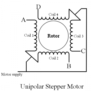
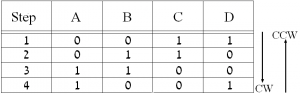
The unipolar stepper motor can be controlled in full step mode or half step mode, the usual method is the full step driving mode. The following table shows driving sequences:
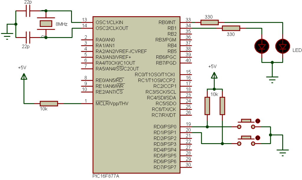
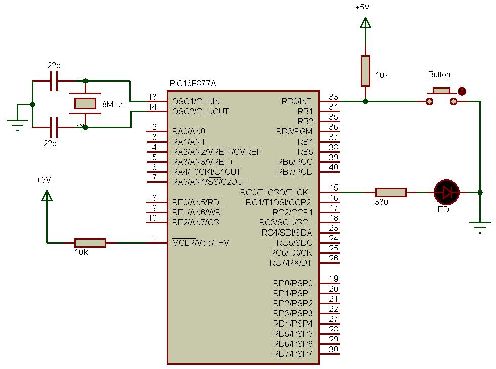
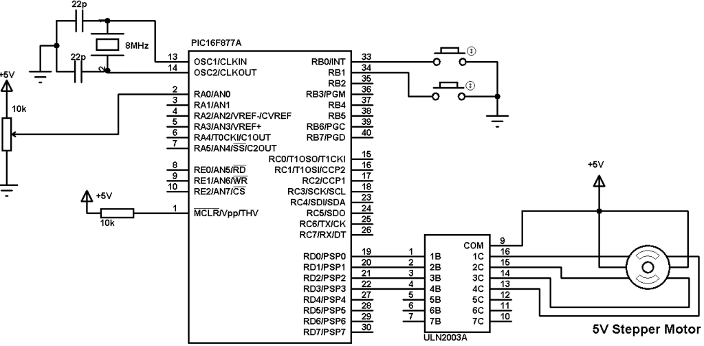
Interfacing PIC16F877A with unipolar stepper motor circuit:
In the circuit there are 2 pushbuttons which are connected to RB0 and RB1 pins, they are used to choose motor rotation direction.
To control the stepper motor speed a potentiometer (10K) is used and it is connected to analog channel 0(AN0).
ULN2003 (or ULN2004) chip is used to energize the stepper motor coils.
The ULN2003 (ULN2004) is a Darlington transistor array which contains seven open collector Darlington pairs with common emitters. For stepper motor controller we need 4 transistors form this chip which means 4 inputs and 4 outputs are needed.
Instead of the ULN2003 chip, another chip can be used which is L293D dual H-bridge circuits as shown in the circuit schematic below.
For the L293D chip VS voltage always +5V and VSS voltage is the same as the motor voltage for example if the motor voltage is 12V VSS should be connected to +12V power supply.
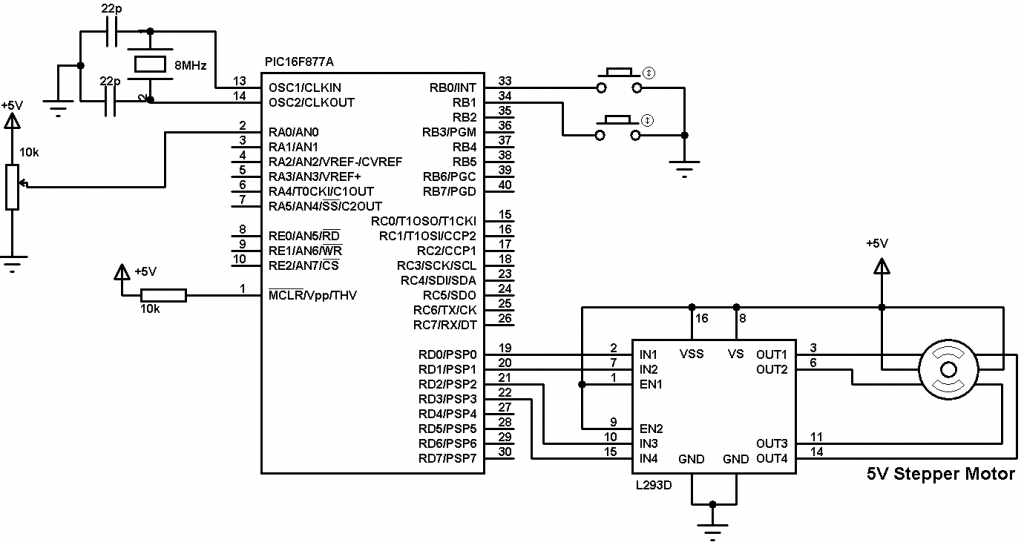
For both circuits the PIC16F877A needs +5V between its VDD and VSS pins.
A pot connected to AN0 is used to control the speed of the stepper motor. The microcontroller reads the analog data from AN0 and uses the digital value to change the delay between motor driving sequences.
1 2 3 4 5 6 7 8 9 10 11 12 13 14 15 16 17 18 19 20 21 22 23 24 25 26 27 28 29 30 31 32 33 34 35 36 37 38 39 40 41 42 43 44 45 46 47 48 49 50 51 52 | // Interfacing PIC16F877A microcontroller with unipolar stepper motor CCS C code #include <16F877A.h> #fuses HS,NOWDT,NOPROTECT,NOLVP #use delay(clock = 8000000) #use fast_io(B) #use fast_io(D) unsigned int8 speed_; void main(){ output_b(0); set_tris_b(0x03); port_b_pullups(TRUE); output_d(0); set_tris_d(0); setup_adc(ADC_CLOCK_DIV_32); // Set ADC conversion time to 32Tosc setup_adc_ports(AN0); // Configure AN0 as analog set_adc_channel(0); // Select channel 0 input delay_ms(100); // Wait 100ms while(TRUE) { output_d(0); while( ! input(PIN_B0)) { speed_ = read_adc(); if(speed_ < 2) speed_ = 2; output_d(0b00000011); delay_ms(speed_); output_d(0b00000110); delay_ms(speed_); output_d(0b00001100); delay_ms(speed_); output_d(0b00001001); delay_ms(speed_); } while( ! input(PIN_B1)) { speed_ = read_adc(); if(speed_ < 2) speed_ = 2; output_d(0b00001001); delay_ms(speed_); output_d(0b00001100); delay_ms(speed_); output_d(0b00000110); delay_ms(speed_); output_d(0b00000011); delay_ms(speed_); } } } |
Interfacing PIC16F877A with unipolar stepper motor video:
The following video shows a hardware circuit for this project.