This article shows how to build a simple real time clock/calendar using PIC16F887 and DS1307 RTC chip.
The DS1307 is an 8-pin integrated circuit uses I2C communication protocol to communicate with master device which is in our case the PIC16F887 microcontroller.
The PIC16F887 microcontroller has an I2C (IIC) module with two pins are used for data transfer. These are the RC3/SCK/SCL pin, which is the clock (SCL), and the RC4/SDI/SDA pin, which is the data (SDA).
The DS1307 can count seconds, minutes, hours, day, date, month and year with leap-year up to year 2100.
The DS1307 receives and transfers data (clock data and calendar data) as BCD format, so after receiving data we have to convert these data into decimal data, and before writing data to the DS1307 we have to convert this data from decimal to BCD format. For example we have the BCD number 33, converting this number into decimal gives 21.
In the CCS C code I used the following line to covert a number ‘x’ from BCD to decimal:
x = (x >> 4) * 10 + (x & 0x0F);
And to go from decimal to BCD I used this line:
x = ((x / 10) << 4) + (x % 10);
Hardware Required:
- PIC16F887 Microcontroller
- DS1307 RTC (datasheet)
- 16×2 LCD screen
- 32.768 KHz crystal
- 10K potentiometer or variable resistor
- 2 x 10K ohm resistors
- 3V Coin cell battery
- 0.1µF Ceramic capacitor (optional)
- 5V Power supply source
- Breadboard
- Jumper wires
DS1307 Interfacing with PIC16F887 circuit:
The circuit diagram of the example is given below.
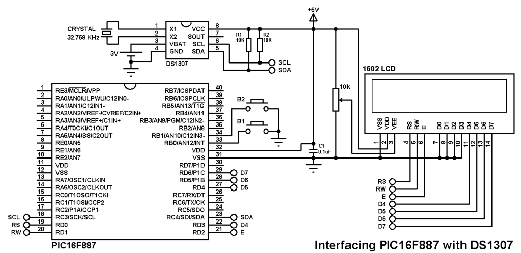
In this example the PIC16F887 MCU uses its internal oscillator and MCLR pin function is disabled.
SCL pin of PIC16F887 (pin number 18) is connected to the SCL pin of the DS1307 (pin number 6) and SDA pin of PIC16F887 (pin number 23) is connected to the SDA pin of the DS1307 (pin number 5).
The 3V cell battery is used to keep the time running if the main power is off.
The two resistors R1 & R2 are pull-up resistors, they are necessary for the I2C protocol.
In the circuit there are two buttons to set time and calendar. The button B1 selects time or calendar parameter (minutes, hours, date, month and year) and B2 increments the selected parameter.
DS1307 Interfacing with PIC16F887 CCS PIC C compiler code:
The code below can display time and calendar where their parameters such as minutes using two push buttons.
This code is tested with version 5.051.
1 2 3 4 5 6 7 8 9 10 11 12 13 14 15 16 17 18 19 20 21 22 23 24 25 26 27 28 29 30 31 32 33 34 35 36 37 38 39 40 41 42 43 44 45 46 47 48 49 50 51 52 53 54 55 56 57 58 59 60 61 62 63 64 65 66 67 68 69 70 71 72 73 74 75 76 77 78 79 80 81 82 83 84 85 86 87 88 89 90 91 92 93 94 95 96 97 98 99 100 101 102 103 104 105 106 107 108 109 110 111 112 113 114 115 116 117 118 119 120 121 122 123 124 125 126 127 128 129 130 131 132 133 134 135 136 137 138 139 140 141 142 143 144 145 146 147 148 149 150 151 152 153 154 155 156 157 158 159 160 161 162 163 164 165 166 167 168 169 170 171 172 173 174 175 | /* Real time clock using PIC16F887 & DS1307 CCS C code Read DS1307 RTC datasheet to understand the code! Internal oscillator used @ 8MHz */ //LCD module connections #define LCD_RS_PIN PIN_D0 #define LCD_RW_PIN PIN_D1 #define LCD_ENABLE_PIN PIN_D2 #define LCD_DATA4 PIN_D3 #define LCD_DATA5 PIN_D4 #define LCD_DATA6 PIN_D5 #define LCD_DATA7 PIN_D6 //End LCD module connections #include <16F887.h> #fuses NOMCLR NOBROWNOUT NOLVP INTRC_IO #use delay(clock = 8MHz) #include <lcd.c> #use fast_io(B) #use I2C(master, I2C1, FAST = 100000) char time[] = "TIME: : : "; char calendar[] = "DATE: / /20 "; unsigned int8 second, minute, hour, date, month, year, day; void ds1307_display(){ // Convert BCD to decimal second = (second >> 4) * 10 + (second & 0x0F); minute = (minute >> 4) * 10 + (minute & 0x0F); hour = (hour >> 4) * 10 + (hour & 0x0F); date = (date >> 4) * 10 + (date & 0x0F); month = (month >> 4) * 10 + (month & 0x0F); year = (year >> 4) * 10 + (year & 0x0F); // End conversion time[12] = second % 10 + 48; time[11] = second / 10 + 48; time[9] = minute % 10 + 48; time[8] = minute / 10 + 48; time[6] = hour % 10 + 48; time[5] = hour / 10 + 48; calendar[14] = year % 10 + 48; calendar[13] = year / 10 + 48; calendar[9] = month % 10 + 48; calendar[8] = month / 10 + 48; calendar[6] = date % 10 + 48; calendar[5] = date / 10 + 48; lcd_gotoxy(1, 1); // Go to column 1 row 1 printf(lcd_putc, time); // Display time lcd_gotoxy(1, 2); // Go to column 1 row 2 printf(lcd_putc, calendar); // Display calendar } void ds1307_write(unsigned int8 address, data_){ i2c_start(); // Start I2C protocol i2c_write(0xD0); // DS1307 address i2c_write(address); // Send register address i2c_write(data_); // Write data to the selected register i2c_stop(); // Stop I2C protocol } void main(){ setup_oscillator(OSC_8MHZ); // Set internal oscillator to 8MHz port_b_pullups(3); // Enable internal pull-ups for RB0 & RB1 lcd_init(); // Initialize LCD module lcd_putc('\f'); // LCD clear while(TRUE){ if(!input(PIN_B0)){ // If RB0 button is pressed lcd_putc('\f'); // LCD clear lcd_gotoxy(5, 1); // Go to column 5 row 1 lcd_putc("Minute:"); delay_ms(200); while(TRUE){ if(!input(PIN_B1)) // If RB1 button is pressed minute++; // Increment minutes if(minute > 59) minute = 0; lcd_gotoxy(8, 2); // Go to column 8 row 2 printf(lcd_putc,"%02u", minute); if(!input(PIN_B0)) break; delay_ms(200); } lcd_putc('\f'); // LCD clear lcd_gotoxy(6, 1); // Go to column 6 row 1 lcd_putc("Hour:"); delay_ms(200); while(TRUE){ if(!input(PIN_B1)) hour++; if(hour > 23) hour = 0; lcd_gotoxy(8, 2); // Go to column 8 row 2 printf(lcd_putc,"%02u", hour); if(!input(PIN_B0)) break; delay_ms(200); } lcd_putc('\f'); // LCD clear lcd_gotoxy(6, 1); // Go to column 6 row 1 lcd_putc("Date:"); delay_ms(200); while(TRUE){ if(!input(PIN_B1)) date++; if(date > 31) date = 1; lcd_gotoxy(8, 2); // Go to column 8 row 2 printf(lcd_putc,"%02u", date); if(!input(PIN_B0)) break; delay_ms(200); } lcd_putc('\f'); // LCD clear lcd_gotoxy(6, 1); // Go to column 6 row 1 lcd_putc("Month:"); delay_ms(200); while(TRUE){ if(!input(PIN_B1)) month++; if(month > 12) month = 1; lcd_gotoxy(8, 2); // Go to column 8 row 2 printf(lcd_putc,"%02u", month); if(!input(PIN_B0)) break; delay_ms(200); } lcd_putc('\f'); // LCD clear lcd_gotoxy(6, 1); // Go to column 6 row 1 lcd_putc("Year:"); lcd_gotoxy(7, 2); // Go to column 7 row 1 lcd_putc("20"); delay_ms(200); while(TRUE){ if(!input(PIN_B1)) year++; if(year > 99) year = 0; lcd_gotoxy(9, 2); // Go to column 9 row 2 printf(lcd_putc,"%02u", year); if(!input(PIN_B0)){ // Convert decimal to BCD minute = ((minute / 10) << 4) + (minute % 10); hour = ((hour / 10) << 4) + (hour % 10); date = ((date / 10) << 4) + (date % 10); month = ((month / 10) << 4) + (month % 10); year = ((year / 10) << 4) + (year % 10); // End conversion ds1307_write(1, minute); // Write minute value to DS1307 ds1307_write(2, hour); ds1307_write(4, date); ds1307_write(5, month); ds1307_write(6, year); ds1307_write(0, 0); //Reset seconds and start oscillator delay_ms(200); break; } delay_ms(200); } } i2c_start(); // Start I2C protocol i2c_write(0xD0); // DS1307 address i2c_write(0); // Send register address i2c_start(); // Restart I2C i2c_write(0xD1); // Initialize data read second = i2c_read(1); // Read seconds from register 0 minute = i2c_read(1); // Read minuts from register 1 hour = i2c_read(1); // Read hour from register 2 day = i2c_read(1); // Read day from register 3 date = i2c_read(1); // Read date from register 4 month = i2c_read(1); // Read month from register 5 year = i2c_read(0); // Read year from register 6 i2c_stop(); // Stop I2C protocol ds1307_display(); // Diaplay time & calendar delay_ms(50); } } |
The following video shows project simulation with Proteus:
Simulation file can be downloaded from this link:
DS1307 + PIC16F887 Simulation


Why did you add 48 after converting bcd to binary code?
time[12] = second % 10 + 48;
pls explain me?
for example: second is bcd 48
48 binary: 0011 0000
0011 0000 >> 4
0000 0011 : 03
3×10= 30
0011 0000 & 0000 1111
0000 0000
30+0 =30
and our second : decimal = 30
so why we are add to 48?
To convert a number that I want to print on the LCD into ASCII format. For example to show 3 on the LCD, I have to send 3 + 48 = 51 to it!
If you add any number with 48 or 0 characters(‘0’), it becomes its ascii code.
In fact, to display a number on an LCD, it must be converted to a string.
degerli paylasim icin tesekkurler bcd den decimal yaparken neden 48 le topladiniz?
Ds1307_wr(D0X0)
{
// What register u seted plze send me
}
Am trying to write the code on pic16f72 with i2c plze send me if this code is available…..pramodp063[at]gmail.com