The datasheet of DS3231 RTC (real time clock) says that it is a low-cost, extremely accurate I2C real-time clock (RTC) with an integrated temperature compensated crystal oscillator (TCXO) and crystal. The DS3231 is much better than the DS1307 which means that it is a very good choice for persons who sell real time clock products.
The DS3231 RTC comes with an internal oscillator which means there is no need for a 32.768KHz crystal oscillator.
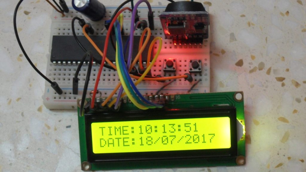
This topic shows the interfacing of the DS3231 RTC with PIC16F887 microcontroller with full adjustment of time and date parameters.
Like the DS1307, the DS3231 uses I2C protocol which uses two lines SCL and SDA. The PIC16F887 has a hardware I2C module where the SCL and SDA pins are mapped to RC3 and RC4 respectively.
Related Projects:
Interfacing DS1307/DS3231 RTC with PIC MCU | MPLAB Projects
Hardware Required:
- PIC16F887 microcontroller
- DS3231 (or DS3232) RTC — Datasheet
- 16×2 LCD screen
- 2 x push button
- 10K ohm variable resistor
- 2 x 10K ohm resistors
- 0.1µF capacitor (decoupling capacitor needed for the DS3231)
- 3V coin cell battery
- 5V voltage source
- Protoboard
- Jumper wires
Interfacing DS3231 with PIC16F887 microcontroller circuit:
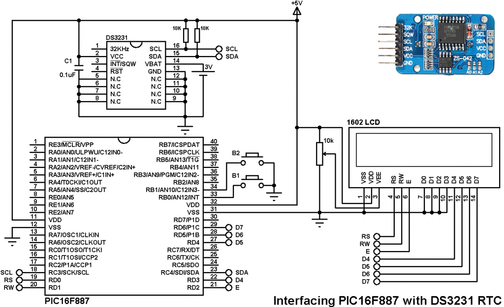
As we can see in the circuit there is a 16×2 LCD to display time and date, this LCD is connected to PORTD. The SCL and SDA pins of the DS3231 are connected to SCL (RC3) and SDA (RC4) pins of the PIC16F887 microcontroller. Two pull-up resistors of 10K are needed for the SCL and SDA lines, if these two resistors are not connected to whole circuit will not work at all and the LCD may not display any thing.
The two buttons which are connected to pins RB0 and RB1, these buttons are used to set the time as well as the date as shown in the videos below.
The 3V cell battery is used as a backup to keep time and date running in case of main power failure. The circuit can work without this battery but its pin (#14) has to be grounded.
The internal oscillator of the PIC16F887 is used and MCLR pin function is disabled.
Interfacing DS3231 with PIC16F887 microcontroller CCS C code:
The C code below is for CCS PIC C compiler (tested with version 5.051).
Please read the DS3231 datasheet to understand the code.
In CCS C it is easy to initialize the I2C module of the PIC microcontroller using the following line:
#use I2C(master, I2C1, FAST = 100000)
Where:
master: set the microcontroller to the master mode
I2C1: use first I2C module (PIC16F887 has only one module)
FAST = 100000 : set the speed to 100KHz
The DS3231 works with BCD format only and to convert the BCD to decimal and vise versa I used the following lines (example for minute variable):
minute = (minute >> 4) * 10 + (minute & 0x0F); // Convert BCD to decimal
minute = ((minute / 10) << 4) + (minute % 10); // Convert decimal to BCD
The full code is as the one below.
1 2 3 4 5 6 7 8 9 10 11 12 13 14 15 16 17 18 19 20 21 22 23 24 25 26 27 28 29 30 31 32 33 34 35 36 37 38 39 40 41 42 43 44 45 46 47 48 49 50 51 52 53 54 55 56 57 58 59 60 61 62 63 64 65 66 67 68 69 70 71 72 73 74 75 76 77 78 79 80 81 82 83 84 85 86 87 88 89 90 91 92 93 94 95 96 97 98 99 100 101 102 103 104 105 106 107 108 109 110 111 112 113 114 115 116 117 118 119 120 121 122 123 124 125 126 127 128 129 130 131 132 133 134 135 136 137 138 139 | /* Real time clock using PIC16F887 & DS3231 (DS3232) CCS C code Read DS3231 RTC datasheet to understand the code! Internal oscillator used @ 8MHz */ //LCD module connections #define LCD_RS_PIN PIN_D0 #define LCD_RW_PIN PIN_D1 #define LCD_ENABLE_PIN PIN_D2 #define LCD_DATA4 PIN_D3 #define LCD_DATA5 PIN_D4 #define LCD_DATA6 PIN_D5 #define LCD_DATA7 PIN_D6 //End LCD module connections #include <16F887.h> #fuses NOMCLR NOBROWNOUT NOLVP INTRC_IO #use delay(clock = 8MHz) #include <lcd.c> #use fast_io(B) #use I2C(master, I2C1, FAST = 100000) char time[] = "TIME: : : "; char calendar[] = "DATE: / /20 "; unsigned int8 i, second, minute, hour, date, month, year; void DS3231_display(){ // Convert BCD to decimal second = (second >> 4) * 10 + (second & 0x0F); minute = (minute >> 4) * 10 + (minute & 0x0F); hour = (hour >> 4) * 10 + (hour & 0x0F); date = (date >> 4) * 10 + (date & 0x0F); month = (month >> 4) * 10 + (month & 0x0F); year = (year >> 4) * 10 + (year & 0x0F); // End conversion time[12] = second % 10 + 48; time[11] = second / 10 + 48; time[9] = minute % 10 + 48; time[8] = minute / 10 + 48; time[6] = hour % 10 + 48; time[5] = hour / 10 + 48; calendar[14] = year % 10 + 48; calendar[13] = year / 10 + 48; calendar[9] = month % 10 + 48; calendar[8] = month / 10 + 48; calendar[6] = date % 10 + 48; calendar[5] = date / 10 + 48; lcd_gotoxy(1, 1); // Go to column 1 row 1 printf(lcd_putc, time); // Display time lcd_gotoxy(1, 2); // Go to column 1 row 2 printf(lcd_putc, calendar); // Display calendar } void blink(){ int8 j = 0; while(j < 10 && input(PIN_B0) && input(PIN_B1)){ j++; delay_ms(25); } } unsigned int8 edit(parameter, xx, yy){ while(!input(PIN_B0)); // Wait until button RB0 is released while(TRUE){ while(!input(PIN_B1)){ // If button RB1 is pressed parameter++; if(i == 0 && parameter > 23) // If hours > 23 ==> hours = 0 parameter = 0; if(i == 1 && parameter > 59) // If minutes > 59 ==> minutes = 0 parameter = 0; if(i == 2 && parameter > 31) // If date > 31 ==> date = 1 parameter = 1; if(i == 3 && parameter > 12) // If month > 12 ==> month = 1 parameter = 1; if(i == 4 && parameter > 99) // If year > 99 ==> year = 0 parameter = 0; lcd_gotoxy(xx, yy); printf(lcd_putc,"%02u", parameter); // Display parameter delay_ms(200); // Wait 200ms } lcd_gotoxy(xx, yy); lcd_putc(" "); blink(); lcd_gotoxy(xx, yy); // Display two spaces printf(lcd_putc,"%02u", parameter); // Display parameter blink(); if(!input(PIN_B0)){ // If button RB0 is pressed i++; // Increament 'i' for the next parameter return parameter; // Return parameter value and exit } } } void main(){ setup_oscillator(OSC_8MHZ); // Set internal oscillator to 8MHz port_b_pullups(3); // Enable internal pull-ups for RB0 & RB1 lcd_init(); // Initialize LCD module lcd_putc('\f'); // LCD clear while(TRUE){ if(!input(PIN_B0)){ // If RB0 button is pressed i = 0; hour = edit(hour, 6, 1); minute = edit(minute, 9, 1); date = edit(date, 6, 2); month = edit(month, 9, 2); year = edit(year, 14, 2); // Convert decimal to BCD minute = ((minute / 10) << 4) + (minute % 10); hour = ((hour / 10) << 4) + (hour % 10); date = ((date / 10) << 4) + (date % 10); month = ((month / 10) << 4) + (month % 10); year = ((year / 10) << 4) + (year % 10); // End conversion // Write data to DS3231 RTC i2c_start(); // Start I2C protocol i2c_write(0xD0); // DS3231 address i2c_write(0); i2c_write(0); // Reset sesonds and start oscillator i2c_write(minute); // Write minute value to DS3231 i2c_write(hour); // Write hour value to DS3231 i2c_write(1); // Write day value (not used) i2c_write(date); // Write date value to DS3231 i2c_write(month); // Write month value to DS3231 i2c_write(year); // Write year value to DS3231 delay_ms(200); // Wait 200ms } i2c_start(); // Start I2C protocol i2c_write(0xD0); // DS3231 address i2c_write(0); // Send register address i2c_start(); // Restart I2C i2c_write(0xD1); // Initialize data read second = i2c_read(1); // Read seconds from register 0 minute = i2c_read(1); // Read minuts from register 1 hour = i2c_read(1); // Read hour from register 2 i2c_read(1); // Read day from register 3 (not used) date = i2c_read(1); // Read date from register 4 month = i2c_read(1); // Read month from register 5 year = i2c_read(0); // Read year from register 6 i2c_stop(); // Stop I2C protocol DS3231_display(); // Display time & calendar delay_ms(50); } } |
The following video shows the interfacing of PIC16F887 with the DS3231 in real hardware circuit:
And the following video shows Proteus simulation:
PIC16F887 and DS3231 RTC Proteus simulation file download:
Download


