The L293D quadruple half-H drivers chip allows us to drive 2 motors in both directions, and with the two PWM modules on the PIC16F887 microcontroller we can easily control the rotation speed of the two motors. (PWM: Pulse Width Modulation).
This small example shows how to implement a control circuit which controls speed and direction of rotation using PIC16F887 microcontroller and L293D IC.
The microcontroller PIC16F887 has one ECCP (Enhanced Capture/Compare/PWM) module and one CCP module. The two modules can be configured as PWM modules to generate two independent PWM signals (always with the same frequency). The speed of each motor can be controlled with the variation of the duty cycle of the PWM signal. The output pins of PWM1 and PWM2 are RC2 and RC1 respectively.
Required Components:
- PIC16F887 microcontroller —> datasheet
- 2 x DC motor (I used motors of 12V)
- L293D motor driver — L293D datasheet
- 2 x 10K ohm potentiometer
- 5V Power source
- 12V Power source (In case of 12V DC motors)
- Breadboard
- Jumper wires
- PIC MCU programmer (PICkit 3, PICkit 4 …)
Two motors control using PIC16F887 and L293D circuit:
Example circuit diagram is shown below.
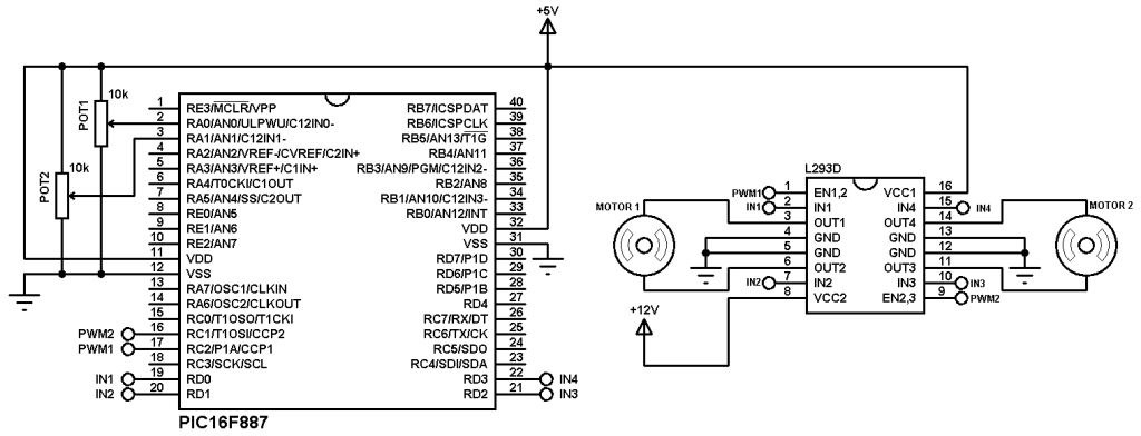
In the circuit there are two potentiometers POT1 and POT2 which are used to control the speed as well as the direction of rotation of motor 1 and motor 2 respectively. POT1 is connected to analog channel 0 (AN0) and POT2 is connected to analog channel 1 (AN1).
PWM1 pin (RC2) is connected to EN1,2 pin (#1) and PWM2 pin (RC1) is connected to EN2,3 pin (#9) of the L293D. The other L293D pins which are IN1, IN2, IN3 and IN4 are connected to RD0, RD1, RD2 and RD3 respectively.
Motor 1 rotation speed is controlled by PWM1 and its direction of rotation is controlled by pins IN1 and IN2. If IN1 and IN2 are zeroes the motor stops, if IN1 = 1 and IN2 = 0 the motor rotates in the one direction, if IN1 = 0 and IN2 = 1 the motor rotates in the other direction.
The same thing for motor 2 with pins PWM2, IN3 and IN4.
In the circuit there are two power supply sources, 5V and 12V. The 5V supplies most of the circuit including the microcontroller whereas the 12V supplies one pin of the L293D (VCC2). The 12V power supply source depends on the motor nominal voltage, for example if the motor voltage is 5V, VCC2 pin should be connected to +5V source.
In this example PIC16F887 uses its internal oscillator and MCLR pin function is disabled.
Two motors control using PIC16F887 and L293D CCS C code:
In this example we’ve two potentiometers POT1 and POT2 connected to AN0 and AN1. Each potentiometer controls speed and rotation direction of one motor. In the code there are three intervals after reading and saving the analog value. The first interval is [ 0, 500 [ which controls the motor speed in the first direction where the maximum speed is when the analog value = 0. The second interval is [ 500, 523 ], here the motor stops. The last interval is ] 523, 1023] where the motor speed is controlled in the other direction and the maximum speed when the analog value = 1023. 10-Bit ADC resolution is used.
Timer2 module is configured to generate PWM signals of 1KHz with a resolution of 8.96 bits :
setup_timer_2(T2_DIV_BY_16, 124, 1);
Where: T2_DIV_BY_16 is Timer2 prescaler
124 is Timer2 preload value
1 is Timer2 postoscaler (not used in calculations)
The PWM frequency can be calculated using the following equation:
Where the PWM frequency = 1/ PWM period
PR2: Timer2 preload value
TOSC = 1/MCU frequency (in this example MCU frequency = 8MHz)
The resolution of the PWM signal can be calculated using the following equation:
Resolution = ———————— bits
log(2)
1 2 3 4 5 6 7 8 9 10 11 12 13 14 15 16 17 18 19 20 21 22 23 24 25 26 27 28 29 30 31 32 33 34 35 36 37 38 39 40 41 42 43 44 45 46 47 48 49 50 51 52 53 54 55 56 57 58 | // Control of 2 motors using PIC16F887 microcontroller CCS C code // Internal oscillator used @ 8MHz // http://simple-circuit.com/ #include <16F887.h> #device ADC = 10 #fuses NOMCLR, NOBROWNOUT, NOLVP, INTRC_IO #use delay(clock = 8MHz) signed int16 i, j; void main(){ setup_oscillator(OSC_8MHZ); // Set internal oscillator to 8MHz setup_adc(ADC_CLOCK_INTERNAL); // ADC module uses its internal oscillator setup_adc_ports(sAN0 | sAN1); // Configure AN0 & AN1 as analog input pins setup_timer_2(T2_DIV_BY_16, 124, 1); // Set PWM frequency to 1KHz with a resolution of 8.96-bit setup_ccp1(CCP_PWM); // Configure CCP1 module as PWM setup_ccp2(CCP_PWM); // Configure CCP2 module as PWM set_pwm1_duty(0); // Set PWM1 duty cycle set_pwm2_duty(0); // Set PWM2 duty cycle while(TRUE){ set_adc_channel(0); // Select channel AN0 delay_ms(100); i = read_adc(); // Read analog value from channel '0' and store it in 'i' set_pwm1_duty(abs(i - 511)); // Set PWM1 duty cycle (abs => absolute value set_adc_channel(1); // Select channel AN1 delay_ms(100); j = read_adc(); // Read analog value from channel '1' and store it in 'j' set_pwm2_duty(abs(j - 511)); // Set PWM2 duty cycle (abs => absolute value if(i > 523){ output_high(PIN_D0); output_low(PIN_D1); } else{ if(i < 500){ output_low(PIN_D0); output_high(PIN_D1); } else{ output_low(PIN_D0); output_low(PIN_D1); } } if(j > 523){ output_high(PIN_D2); output_low(PIN_D3); } else{ if(j < 500){ output_low(PIN_D2); output_high(PIN_D3); } else{ output_low(PIN_D2); output_low(PIN_D3); } } } } |
Video:
Related project:
Two DC motors control from IR remote control – CCS C


