This post shows how to control a sensorless brushless DC (BLDC) motor using PIC16F887 8-bit microcontroller, or let’s say how to build a DIY ESC (Electronic speed controller using PIC16F887).
Basically there are two types of brushless motors: sensored and sensorless. Sensored BLDC motors come with three hall effect sensors which are used to detect (know) the position of the rotor (where it is located) at any moment, that’s why they called sensored.
The second type is: sensorless BLDC motors. Sensorless BLDC motor has no sensor to detect the rotor position, it has only 3 wires for power (3-phase). The commutation of sensorless BLDC motor is based on the BEMF (Back Electromotive Force) produced in the stator windings.
The main advantage of the sensorless BLDC motor control is lower system cost and the main disadvantage is the motor must be moving at minimum rate to produce sufficient BEMF to be sensed.
How it works:
When the BLDC motor rotates, each winding (3 windings) generates BEMF opposes the main voltage. The 3 generated BEMF signals are 120° out of phase which is the same as the hall effect sensor signals. The figure below shows the relationship between the hall effect signals and the BEMF signals:
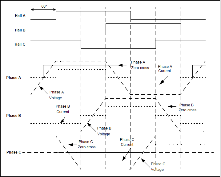
As shown in the figure above, the BEMF signals are not synchronized with the hall effect sensor signals (phase shift of 30°). In every energizing sequence, two windings are energized (one connected to positive and the other to negative) and the third winding is left open (floating). The floating winding is used to detect the zero crossing, thus, the combination of all 3 zero cross over point are used to generate the energizing sequence. Totally we’ve 6 events:
Phase A zero crossing: from high to low and from low to high
Phase B zero crossing: from high to low and from low to high
Phase C zero crossing: from high to low and from low to high
How to detect the zero crossing:
The easiest way to detect the zero crossing events is by using comparators. The comparator has 3 main terminals: 2 inputs (positive and negative) and an output. Comparator output is logic high if the positive voltage is greater than the negative voltage, and logic low if the positive voltage is lower than the negative voltage.
Basically 3 comparators are needed for this project, connections are done as shown in the figure below (example for phase B). Each phase requires a similar circuit:
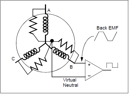
The virtual natural point is the same for all the 3 comparators, it is generated using 3 resistors. When the BEMF generated in the floating (open) winding crosses the zero point towards positive side, the comparator output makes a transition from low-to-high. When the BEMF generated in the floating winding crosses the zero point towards negative side, the comparator output makes a transition from high-to-low. By having three such comparator circuits, one on each of the phases gives three digital signals corresponding to the BEMF signal in the windings. The combination of these three signals is used to derive the commutation sequence.
The PIC16F887 has two analog comparators, one of them is enough for this project. The one will be used is comparator 1.
Components Required:
- PIC16F887 microcontroller – datasheet
- Brushless DC motor
- 6 x 06N03LA N-type mosfet (or equivalent) – datasheet
- 3 x IR2101 (or IR2101S) gate driver IC – datasheet
- 6 x 33k ohm resistor
- 3 x 10k ohm resistor
- 6 x 10 ohm resistor
- 3 x IN4148 diode
- 3 x 10uF capacitor
- 3 x 2.2uF capacitor
- 20 MHz crystal oscillator
- 2 x 22pF ceramic capacitor
- 10k ohm potentiometer
- 12V source
- 5V source
- Breadboard
- Jumper wires
As an addition we need:
- CCS C compiler to compile the C code below
- PIC programmer such as PICkit 3, PICkit 2 ……
- MPLAB IPE software
Brushless DC motor control with PIC16F887 microcontroller circuit:
Project circuit schematic diagram is shown below.
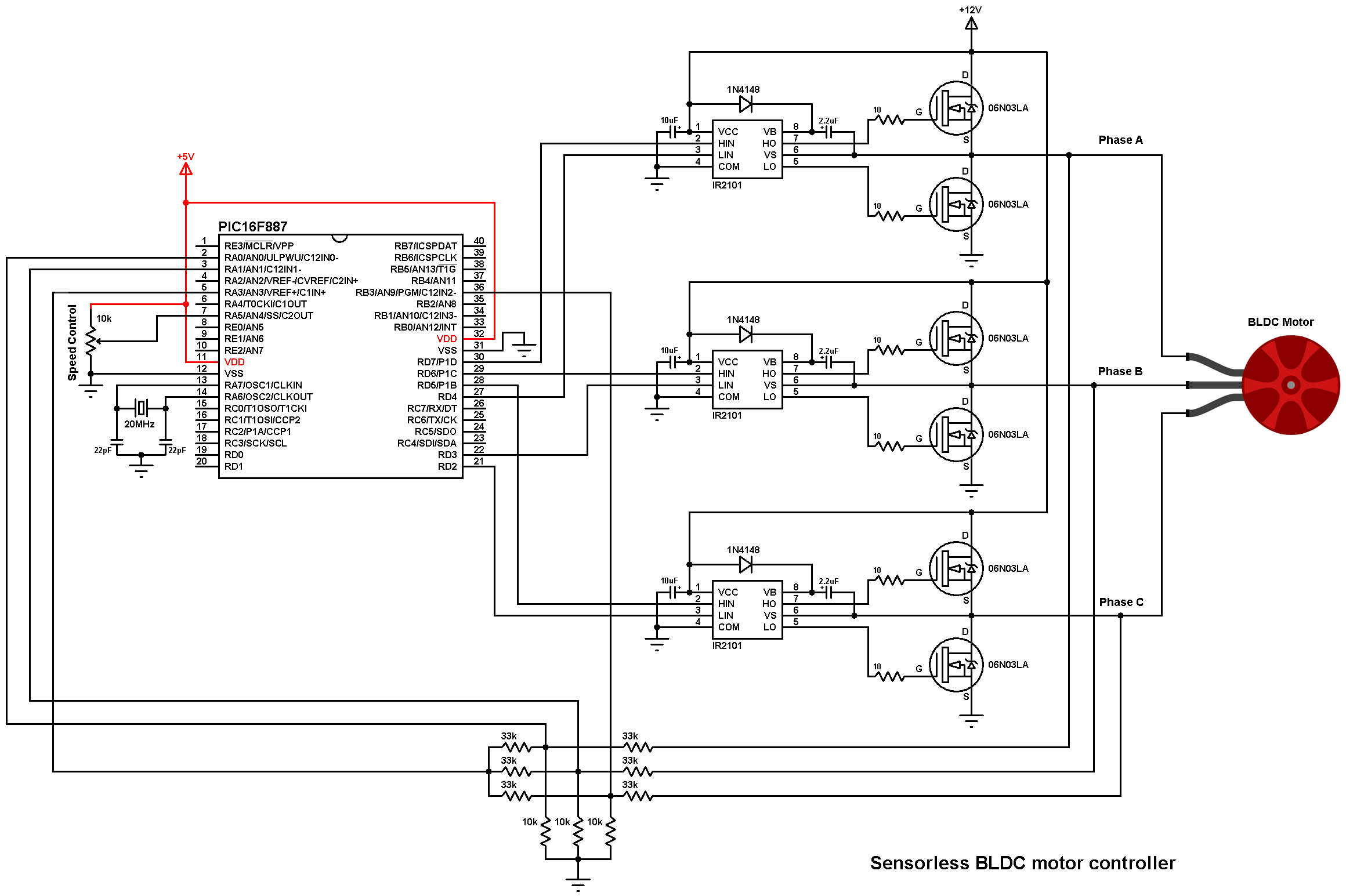
Note that all grounded terminals are connected together.
As known the brushless motors are 3-phase motors. In the circuit diagram above the 3 phases are named: Phase A, Phase B and Phase C.
In this project we need two power sources, the first one with 5V and used to power the microcontroller. The other one with 12V which is used to power the three-phase bridge and therefore the BLDC motor.
The first three 33k (connected to motor phases) and the three 10k resistors are used as voltage dividers, because we can not supply the microcontroller with 12V, the other three 33k resistors generate the virtual natural point. The virtual natural point is connected to pin RA3 (#5) which is comparator 1 positive input.
PIC16F887 microcontroller has two analog comparators, one of them is enough for this project, so I chose comparator 1. The positive input of this comparator is C1IN+ (pin #5) and the negative input can be C12IN0- (pin #2), C12IN1- (pin #3), C12IN2- (pin #36) or C12IN3- (pin #34). Therefore, I connected the virtual natural point to the positive pin of the analog comparator C1IN+ (pin #5), phase A BEMF to C12IN0- (pin #2), C12IN1- (pin #3) and phase C BEMF to C12IN2- (pin #36). Each time the comparator compares the virtual point with the BEMF of one phase (done in the software). This minimizes the hardware needed and simplifies the circuit.
The IR2101 chips are used to control high side and low side mosfets of each phase. The switching between the high side and the low side is done according to the control lines HIN and LIN. The figure below shows input and output timing diagram:
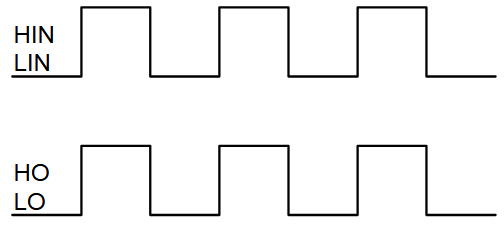
The HIN lines of the three IR2101 are connected to pins: P1D (RD7), P1C (RD6) and P1B (RD5) respectively for phase A, phase B and phase C, whereas the LIN lines are connected to pins: RD4, RD3 and RD2.
The PIC16F887 has one CCP module (Capture/Compare/PWM module) and one ECCP module (Enhanced CCP module). With the ECCP module we can generate 4 PWM signals with the same frequency and controlled by one duty cycle (we need 3 PWM signals). In this project I applied 3 PWM signals to high side mosfets only (one PWM active at a time).
The speed of the BLDC motor is controlled by a potentiometer connected to analog channel AN4 (pin #7).
The PIC16F887 runs with 20MHz crystal oscillator (5 MIPS), MCLR pin function is disabled.
Brushless DC motor control with PIC16F887 microcontroller C code:
The C code was tested with CCS C compiler version 5.051. The compiler may give a warning, it is not a problem at all, just ignore it!
Timer2 module is configured to give a PWM signal with frequency of 19.53 KHz and resolution of 10 bits. The configuration line is:
setup_timer_2(T2_DIV_BY_1, 255, 1);
where Timer2 prescaler = 1, preload (PR2) = 255
PWM frequency and resolution can be calculated using the functions below (Fosc = 20 MHz):
PWM_freqency = Fosc/{[(PR2) + 1] * 4 * (TMR2 Prescaler Value)} = 19.53 KHz
Resolution = log[4(PR2 + 1)]/log(2) = 10 bits
Full CCS C code is below.
1 2 3 4 5 6 7 8 9 10 11 12 13 14 15 16 17 18 19 20 21 22 23 24 25 26 27 28 29 30 31 32 33 34 35 36 37 38 39 40 41 42 43 44 45 46 47 48 49 50 51 52 53 54 55 56 57 58 59 60 61 62 63 64 65 66 67 68 69 70 71 72 73 74 75 76 77 78 79 80 81 82 83 84 85 86 87 88 89 90 91 92 93 94 95 96 97 98 99 100 101 102 103 104 105 106 107 108 109 110 111 112 113 114 115 116 117 118 119 120 121 122 123 124 125 126 127 128 | /* * Sensorless brushless DC ( BLDC ) motor control with PIC16F887 microcontroller. * C Code for CCS C compiler. * This is a free software with NO WARRANTY. * http://simple-circuit.com/ */ #define PWM_MIN_DUTY 80 #define PWM_START_DUTY 200L // Letter L for 'Long' (16-bit number) #include <16F887.h> #device ADC = 10 #fuses NOMCLR, HS, NOBROWNOUT, NOLVP #use delay(clock = 20MHz) #use fast_io(D) void AH_BL(); void AH_CL(); void BH_CL(); void BH_AL(); void CH_AL(); void CH_BL(); void bldc_move(); int8 bldc_step = 0; int16 motor_speed; #INT_COMP void comparator_isr() { // Comparator ISR // BEMF debounce for(int8 j = 0; j < 20; j++) { if(bldc_step & 1) { if(!C1OUT) j -= 1; } else { if(C1OUT) j -= 1; } } bldc_move(); clear_interrupt(INT_COMP); // Clear comparators interrupt flag } void bldc_move(){ // BLDC motor commutation function switch(bldc_step){ case 0: AH_BL(); setup_comparator(CP1_B3_A3); // Sense BEMF C (pin RA3 positive, RB3 negative) break; case 1: AH_CL(); setup_comparator(CP1_A1_A3); // Sense BEMF B (pin RA3 positive, RA1 negative) break; case 2: BH_CL(); setup_comparator(CP1_A0_A3); // Sense BEMF A (pin RA3 positive, RA0 negative) break; case 3: BH_AL(); setup_comparator(CP1_B3_A3); // Sense BEMF C (pin RA3 positive, RB3 negative) break; case 4: CH_AL(); setup_comparator(CP1_A1_A3); // Sense BEMF B (pin RA3 positive, RA1 negative) break; case 5: CH_BL(); setup_comparator(CP1_A0_A3); // Sense BEMF A break; } bldc_step++; if(bldc_step >= 6) bldc_step = 0; } void main(){ output_d(0); // PORTD initial state set_tris_d(0); // Configure all PORTD pins as outputs setup_timer_2(T2_DIV_BY_1, 255, 1); // Set PWM frequency to 19.53KHz and 10-bit resolution setup_adc(ADC_CLOCK_INTERNAL); // Set ADC module clock source to internal setup_adc_ports(sAN4); // Configure AN4 pin as analog set_adc_channel(4); // Select channel 4 (AN4) ENABLE_INTERRUPTS(GLOBAL); // Enable global interrupts ENABLE_INTERRUPTS(PERIPH); // Enable periphiral interrupts clear_interrupt(INT_COMP); // Clear comparators interrupt flag // Motor start set_pwm1_duty(PWM_START_DUTY); // Set PWM duty cycle int16 i = 5000; while(i > 100) { delay_us(i); bldc_move(); i = i - 20; } ENABLE_INTERRUPTS(INT_COMP); // Enable comparators interrupt while(TRUE) { READ_ADC(ADC_START_ONLY); // Start analog conversion delay_ms(50); // wait 50 ms motor_speed = read_adc(ADC_READ_ONLY); // Read conversion result if(motor_speed < PWM_MIN_DUTY) motor_speed = PWM_MIN_DUTY; set_pwm1_duty(motor_speed); // Set PWM duty cycle } } void AH_BL(){ setup_ccp1(CCP_OFF); output_d(0x08); setup_ccp1(CCP_PWM| CCP_PULSE_STEERING_D); // PWM output on pin P1D (RD7), others OFF } void AH_CL(){ output_d(0x04); } void BH_CL(){ setup_ccp1(CCP_OFF); output_d(0x04); setup_ccp1(CCP_PWM| CCP_PULSE_STEERING_C); // PWM output on pin P1C (RD6), others OFF } void BH_AL(){ output_d(0x10); } void CH_AL(){ setup_ccp1(CCP_OFF); output_d(0x10); setup_ccp1(CCP_PWM| CCP_PULSE_STEERING_B); // PWM output on pin P1B (RD5), others OFF } void CH_BL(){ output_d(0x08); } |
Finally this video shows a simple hardware circuit of the project:
Related Projects:
Sensorless BLDC motor control with PIC microcontroller and mikroC
Brushless DC motor controller using Arduino and IR2101
References:
Microchip AN970 document
https://www.microchip.com/


Hi I’ve working this for weeks. Completed the hardware part, but I get the following error while executing the CCS code.
Error 128 “C:\Program Files (x86)\PICC\Drivers\stdint.h” Line 19(9,15): A #DEVICE required before this line.
These are the starting few lines of the stdint.h file that got opened.
///////////////////////////////////////////////////////////////////////////
//// ////
//// stdint.h ////
//// ////
//// Standard integer definitions. ////
//// ////
///////////////////////////////////////////////////////////////////////////
//// (C) Copyright 1996,2008 Custom Computer Services ////
//// This source code may only be used by licensed users of the CCS C ////
//// compiler. This source code may only be distributed to other ////
//// licensed users of the CCS C compiler. No other use, reproduction ////
//// or distribution is permitted without written permission. ////
//// Derivative programs created using this software in object code ////
//// form are not restricted in any way. ////
///////////////////////////////////////////////////////////////////////////
#ifndef _STDINT
#define _STDINT
//////////// exact width
typedef signed int8 int8_t;
typedef unsigned int8 uint8_t;
typedef signed int16 int16_t;
typedef unsigned int16 uint16_t;
typedef signed int32 int32_t;
typedef unsigned int32 uint32_t;
Kindly help on this issue. I’m really in need of ot
what might be the reason for the motor not to be running even though the circuit is connected correctly? I gave changed the MOSFETs to IRFZ44N. with 5V for MCU and 12V for the MOSFETs.
If I use ir2104 as in the video, what modification should I do in the code? please help me
Please give the required C program if we want to use the MCU PIC16F877A, instead of PIC16F887. This is because PIC16F887 is not available in the market, but PIC16F877F is readily available.
Thank you for your prompt response, much appreciated!
I have indeed experimented with different values with no good results.
Your circuit voltage devider values are: R1(33K), R2(10K).
I have been attempting the followings values R1(22K), R2(1K, 2.7K, or 10K).
Can you please advise/recommend/confirm the accurate voltage divider values I can use with motor voltage at 20V, 42V and 400V?
Greeting, I have followed your desing and it runs well when supplying both the uC 5V, the driver circuit with 12V nad Motorvolatage with 12V, but if I only increase the Motor voltage to 20V or more then the motor does not run well, no speed change, andit it stops running after few seconds, please advise (is the problem with ground/earth?).
YOU NEED TO CHANGE VOLTAGE DIVIDER USE FOR BEMF SENSING .
Thank you for your prompt response, much appreciated!
I have indeed experimented with different values with no good results.
Your circuit voltage devider values are: R1(33K), R2(10K).
I have been attempting the followings values R1(22K), R2(1K, 2.7K, or 10K).
Can you please advise/recommend/confirm the accurate voltage divider values I can use with motor voltage at 20V, 42V and 400V?
el sistema no funciona porque el divisor de las resistencias está pensado para 12 V. deberías modificar los divisores (33k-10k)
Code*
We need to change or modify the code .
I want to use hall sensors in this circuit for that we need to change the as well can you guide us in this ?
I’m looking forward to hearing from you
Hello, I have got sensorless BLDC motor up to 220V. It’s possible to modify the circuit for this motor? Thank you.
Hello. Which mosfet can I use instead of 06N03LA mosfet
a lot of mosfet you can use irf3205 – irfz44n – irf1404
I can’t compile this C code. I need .hex please help !
Compile the C code with CCS C compiler and you’ll get the .hex file!
Otherwise, compile the C code provided in this topic with mikroC PRO for PIC compiler:
Sensorless BLDC motor control with PIC microcontroller and mikroC
I cant load C code on PIC 16f887, Please send me file .hex of project
X2… I can’t compile this C code. I need .hex
Do you have an idea if we would like to do the direction change.
By changing any two wire of Motor
by changing any two-phase wires among themselves, going to the motor supply .