This project shows how to implement a simple temperature measurement station using PIC18F4550 microcontroller and DS18B20 digital temperature sensor.
The PIC18F4550 MCU reads temperature from the DS18B20 sensor and print its value (in °C) on SSD1306 OLED display (128×64 pixel).
CCS C compiler is used in this project.
In this project the SSD1306 OLED is configured to work in I2C mode, make sure that your display is configured to work in I2C mode, some displays need jumper placing or some soldering.
To see how to interface PIC18F4550 MCU with SSD1306 OLED display (I2C mode), take a look at the following project:
Interfacing PIC18F4550 with SSD1306 OLED
The DS18B20 temperature sensor is a 3-pin electronic component (like a simple transistor) from Maxim (formerly Dallas) which uses 1-wire protocol to communicate with master device (microprocessor, microcontroller ….). Each DS18B20 device has a unique 64-bit serial code, which allows multiple DS18B20s to function on the same 1-wire bus and controlled with one master device.
The DS18B20 sensor provides 9-bit to 12-bit Celsius temperature measurement resolution (programmable resolution).
Hardware Required:
- PIC18F4550 microcontroller —-> datasheet
- SSD1306 OLED display with 128×64 pixel resolution
- DS18B20 temperature sensor —-> datasheet
- 4.7k ohm resistor
- 5V source
- Breadboard
- Jumper wires

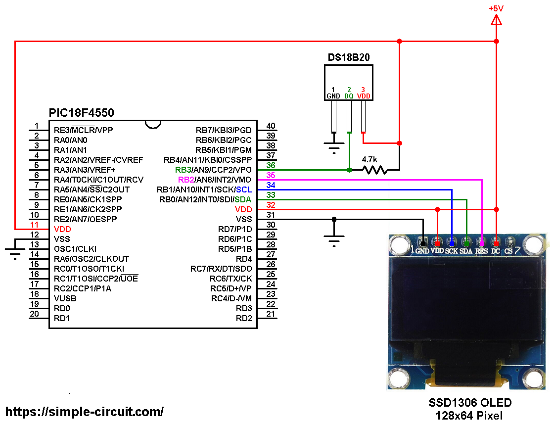
PIC18F4550 with SSD1306 OLED and DS18B20 sensor circuit:
The image below shows project circuit diagram.
The DS18B20 sensor has 3 pins (from left to right): GND, data pin and VCC (or VDD) where:
GND: connected to circuit ground (0V),
data pin: connected to PIC18F4550 RB3 (#36) and
VCC: sensor power supply pin, connected to circuit +5V.
A pull-up resistor of 4.7k ohm is required because the DS18B20 has an open drain output.
All the grounded terminals are connected together.
The SSD1306 OLED display is connected to the circuit as follows:
SSD1306 OLED GND goes to circuit ground,
SSD1306 OLED VDD is connected to circuit 5V,
SSD1306 OLED SDA pin (serial data) to pin RB0 (PIC18F4550 hardware I2C SDA pin),
SSD1306 OLED SCK pin (serial clock) to pin RB1 (PIC18F4550 hardware I2C SCL pin),
SSD1306 OLED RES pin (reset) to pin RB2.
The SSD1306 OLED display DC pin is connected to VDD which means I2C slave address of the device is 0x7A. If the DC pin is connected to ground (GND) then the I2C slave address becomes 0x78.
In this project the PIC18F4550 microcontroller runs with its internal oscillator @ 8 MHz, MCLR pin is configured as an input pin.
PIC18F4550 with SSD1306 OLED and DS18B20 sensor C code:
The C code below is for CCS C compiler, it was tested with version 5.051.
To be able to compile the C code below with no error, a driver for the SSD1306 OLED display is required, it’s full name (with extension) is SSD1306OLED.C, for more information about this driver, visit the following post:
SSD1306 OLED Library for CCS C compiler
It can be downloaded also from the link below:
SSD1306 OLED Library download
after the download, add the driver file to project folder or CCS C compiler drivers folder.
Programming hints:
The SSD1306 OLED reset pin and DS18B20 sensor data pin are defined in the code as shown below:
1 2 3 4 5 | // SSD1306 OLED reset pin definition #define SSD1306_RST PIN_B2 // DS18B20 data pin definition #define DS18B20_PIN PIN_B3 |
Functions used in the code:
int1 ds18b20_start(): used to know if the DS18B20 sensor is correctly connected to the circuit, returns 1 if OK and 0 if error.
ds18b20_write_bit(int1 value): writes (sends) 1 bit to the DS18B20 sensor, the bit is value which may be 1 or 0.
ds18b20_write_byte(int8 value): writes 1 byte (8 bits) to the DS18B20 sensor, this function is based on the previous function. This function writes LSB first.
int1 ds18b20_read_bit(void): reads 1 bit from the DS18B20 sensor, returns the read value (1 or 0).
int8 ds18b20_read_byte(void): reads 1 byte from the DS18B20 sensor, this function is based on the previous function. This function reads LSB first.
int1 ds18b20_read(int16 *raw_temp_value): reads the temperature raw data which is 16-bit long (two 8-bit registers), the data is stored in the variable raw_temp_value, returns 1 if OK and 0 if error.
The value of the temperature in degree Celsius is equal to the raw value divided by 16 (in case of 12-bit resolution). The default resolution of the DS18B20 is 12 bits.
Note that 1/16 = 0.0625.
Temperature value is printed on the SSD1306 OLED. If there is a problem with the sensor, the screen will display ERROR instead of the temperature value.
Full CCS C code:
1 2 3 4 5 6 7 8 9 10 11 12 13 14 15 16 17 18 19 20 21 22 23 24 25 26 27 28 29 30 31 32 33 34 35 36 37 38 39 40 41 42 43 44 45 46 47 48 49 50 51 52 53 54 55 56 57 58 59 60 61 62 63 64 65 66 67 68 69 70 71 72 73 74 75 76 77 78 79 80 81 82 83 84 85 86 87 88 89 90 91 92 93 94 95 96 97 98 99 100 101 102 103 104 105 106 107 108 109 110 111 112 113 114 115 116 117 118 119 120 121 122 123 124 125 126 127 128 129 130 131 132 133 134 135 136 137 138 139 140 141 142 143 144 145 146 147 148 149 150 151 | /* * Interfacing PIC18F4550 microcontroller with SSD1306 OLED (128x64 Pixel) * and DS18B20 digital temperature sensor. * C Code for CCS C compiler. * This is a free software with NO WARRANTY. * http://simple-circuit.com/ */ // SSD1306 OLED reset pin definition #define SSD1306_RST PIN_B2 // DS18B20 data pin definition #define DS18B20_PIN PIN_B3 #include <18F4550.h> #fuses NOMCLR, NOWDT, NOPROTECT, NOLVP #use delay(internal = 8MHz) #use I2C(MASTER, I2C1, FAST = 400000, stream = SSD1306_STREAM) // initialize I2C // include SSD1306 OLED driver source code #include <SSD1306OLED.c> int1 ds18b20_start() { int1 ret = 0; output_low(DS18B20_PIN); // send reset pulse to the DS18B20 sensor output_drive(DS18B20_PIN); delay_us(500); // wait 500 us output_float(DS18B20_PIN); delay_us(100); // wait to read the DS18B20 sensor response if (!input(DS18B20_PIN)) { ret = 1; // DS18B20 sensor is present delay_us(400); // wait 400 us } return(ret); } void ds18b20_write_bit(int1 value) { output_low(DS18B20_PIN); output_drive(DS18B20_PIN); delay_us(2); output_bit(DS18B20_PIN, value); delay_us(80); output_float(DS18B20_PIN); delay_us(2); } void ds18b20_write_byte(int8 value) { int8 i; for(i = 0; i < 8; i++) ds18b20_write_bit(bit_test(value, i)); } int1 ds18b20_read_bit(void) { int1 value; output_low(DS18B20_PIN); output_drive(DS18B20_PIN); delay_us(2); output_float(DS18B20_PIN); delay_us(5); value = input(DS18B20_PIN); delay_us(100); return value; } int8 ds18b20_read_byte(void) { int8 i, value = 0; for(i = 0; i < 8; i++) shift_right(&value, 1, ds18b20_read_bit()); return value; } int1 ds18b20_read(int16 *raw_temp_value) { if (!ds18b20_start()) // send start pulse return FALSE; ds18b20_write_byte(0xCC); // send skip ROM command ds18b20_write_byte(0x44); // send start conversion command while(ds18b20_read_byte() == 0); // wait for conversion complete if (!ds18b20_start()) // send start pulse return FALSE; // return 0 if error ds18b20_write_byte(0xCC); // send skip ROM command ds18b20_write_byte(0xBE); // send read command *raw_temp_value = ds18b20_read_byte(); // read temperature LSB byte and store it on raw_temp_value LSB byte *raw_temp_value |= (int16)(ds18b20_read_byte()) << 8; // read temperature MSB byte and store it on raw_temp_value MSB byte return TRUE; // OK --> return 1 } // main function void main() { delay_ms(1000); // wait 1 second // initialize the SSD1306 OLED with an I2C addr = 0x7A (default address) SSD1306_Begin(SSD1306_SWITCHCAPVCC, SSD1306_I2C_ADDRESS); SSD1306_ClearDisplay(); // clear the display buffer SSD1306_SetTextWrap(false); // disable text wrap SSD1306_GotoXY(4, 0); // move cursor to position (4, 0) pixel SSD1306_Print("PIC18F4550 + DS18B20"); SSD1306_GotoXY(28, 14); // move cursor to position (28, 14) pixel SSD1306_Print("SSD1306 OLED"); SSD1306_GotoXY(29, 33); // move cursor to position (29, 33) pixel SSD1306_Print("TEMPERATURE:"); SSD1306_Display(); SSD1306_TextSize(2); // text size = 2 unsigned int16 ds18b20_temp; while(TRUE) { SSD1306_GotoXY(1, 50); if(ds18b20_read(&ds18b20_temp)) { if (ds18b20_temp & 0x8000) // if temperature < 0 { ds18b20_temp = ~ds18b20_temp + 1; // change temperature value to positive form printf(SSD1306_Print, "-%02Lu.%04Lu C", (ds18b20_temp/16) % 100, (ds18b20_temp & 0x0F) * 625); } else { // otherwise (temperature >= 0) if (ds18b20_temp/16 >= 100) // if temperature >= 100 °C printf(SSD1306_Print, "%03Lu.%04Lu C", ds18b20_temp/16, (ds18b20_temp & 0x0F) * 625); else // otherwise ( 0 <= temperature < 100) printf(SSD1306_Print, " %02Lu.%04Lu C", ds18b20_temp/16, (ds18b20_temp & 0x0F) * 625); } // print degree symbol ( ° ) SSD1306_DrawCircle(104, 52, 2); } else // sensor error! SSD1306_Print(" ERROR "); SSD1306_Display(); delay_ms(1000); // wait a second } } // end of code. |
The following small video shows the result of my hardware circuit:


