With PIC18F4550 8-bit microcontroller we can easily build a simple ESC (Electronic Speed Controller) for brushless DC motors. This topic shows how did I made an ESC using the PIC18F4550 microcontroller and few other components.
First the brushless dc motor is a 3-phase motor comes in two main types: sensored and sensorless. The sensorless BLDC motor control technique is based on the BEMF (Back Electromotive Force) produced in the stator windings.
For more details about the sensorless BLDC motor and how to control it, see the following project:
Brushless DC motor control with PIC16F887 microcontroller
Hardware Required:
- PIC18F4550 microcontroller —> datasheet
- Brushless DC motor
- 6 x 06N03LA N-type mosfet (or equivalent) – datasheet
- 3 x IR2101 (or IR2101S) gate driver IC – datasheet
- LM339 quad comparator IC
- 6 x 33k ohm resistor
- 6 x 10k ohm resistor
- 6 x 10 ohm resistor
- 3 x IN4148 diode
- 3 x 10uF capacitor
- 3 x 2.2uF capacitor
- 8 MHz crystal oscillator
- 2 x 22pF ceramic capacitor
- 10k ohm potentiometer
- 12V source
- 5V source
- Breadboard
- Jumper wires
- PIC MCU programmer (PICkit 3, PICkit 4 …)
Sensorless BLDC motor controller using PIC18F4550 microcontroller circuit:
Circuit schematic diagram is shown below.
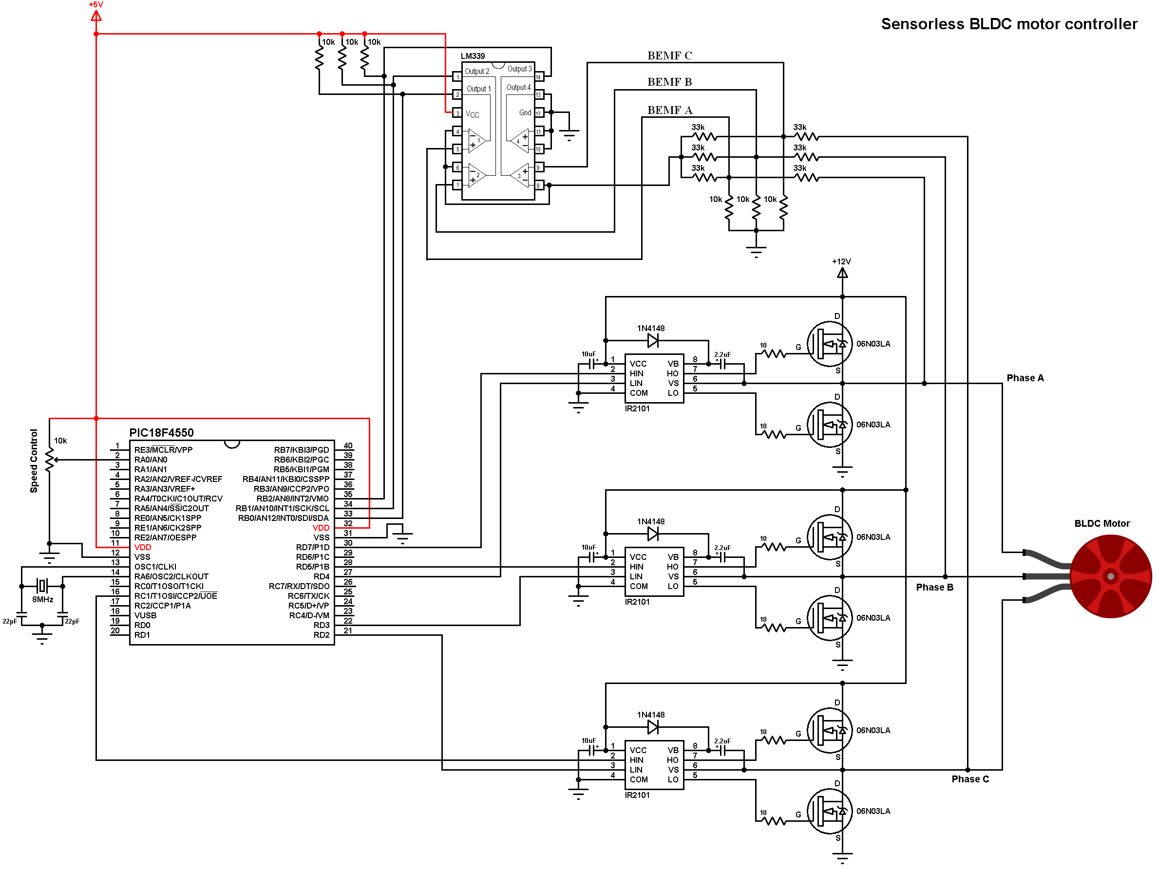
Note that all grounded terminals are connected together.
As known the brushless motors are 3-phase motors. In the circuit diagram above the 3 phases are named: Phase A, Phase B and Phase C.
In this project we need two power sources, the first one with 5V and used to power the microcontroller. The other one with 12V which is used to power the three-phase bridge and therefore the BLDC motor.
The first three 33k (connected to motor phases) and the three 10k resistors are used as voltage dividers, the other three 33k resistors generate the virtual natural point.
In this project we need 3 comparators to compare the BEMF of each phase with respect to the virtual natural point because we need to detect the zero crossing of each phase, here I used the LM339 quad comparator chip. The virtual point is connected to the inverting input ( – ) of the three comparators as shown in the circuit diagram above. BEMF A is connected to the non-inverting pin ( + ) of comparator number 1, BEMF B is connected to the positive terminal of comparator 2 and BEMF C is connected to the positive terminal of comparator 3. Comparator 4 is not used and all its terminals should be grounded.
As known the comparator output is logic 1 if the non-inverting voltage is greater than the inverting voltage and vice versa.
The LM339 outputs are open collector which means a pull up resistors are needed, for that I used three 10 K ohm resistors.
The outputs of the 3 comparators are connected to PIC18F4550 external interrupt pins INT0 (RB0), INT1 (RB1) and INT2 (RB2) respectively for BEMF A, BEMF B and BEMF C.
The PIC18F4550 microcontroller has one CCP (Capture/Compare/PWM) module and one ECCP (Enhanced CCP) module. The CCP module can generate one PWM signal on pin RC1. The ECCP module can generate two PWM signals on pin RD5 (full bridge reverse mode) and pin RD7 (full bridge forward mode). So with that we have 3 PWM signals which are then connected to HIN pins of the IR2101 gate drivers (pwming high side mosfets only).
In this project the PIC18F4550 microcontroller runs with 8 MHz crystal oscillator and MCLR pin function is disabled.
C Code:
The C code was tested with CCS C compiler version 5.051. The compiler may give a warning, it is not a problem at all, just ignore it!
As mentioned above the microcontroller runs with 8 MHz crystal oscillator, in the code the PLL is enabled (PLL2) which makes the CPU runs at 48 MHz (12 MIPS).
Timer2 module is configured to give a PWM signal with frequency of 46.875 KHz and resolution of 10 bits. The configuration line is:
setup_timer_2(T2_DIV_BY_1, 255, 1);
where Timer2 prescaler = 1, preload (PR2) = 255
PWM frequency and resolution can be calculated using the functions below (Fosc = 48 MHz):
PWM_freqency = Fosc/{[(PR2) + 1] * 4 * (TMR2 Prescale Value)} = 46.875 KHz
Resolution = log[4(PR2 + 1)]/log(2) = 10 bits
All PWM signals have the same frequency since they use the same timer module (Timer2).
Full C code is below with some descriptions through comments.
1 2 3 4 5 6 7 8 9 10 11 12 13 14 15 16 17 18 19 20 21 22 23 24 25 26 27 28 29 30 31 32 33 34 35 36 37 38 39 40 41 42 43 44 45 46 47 48 49 50 51 52 53 54 55 56 57 58 59 60 61 62 63 64 65 66 67 68 69 70 71 72 73 74 75 76 77 78 79 80 81 82 83 84 85 86 87 88 89 90 91 92 93 94 95 96 97 98 99 100 101 102 103 104 105 106 107 108 109 110 111 112 113 114 115 116 117 118 119 120 121 122 123 124 125 126 127 128 129 130 131 132 133 134 135 136 137 138 139 140 141 142 143 144 145 146 147 148 149 150 151 152 153 154 155 156 157 158 159 160 161 162 163 164 165 166 167 168 169 170 171 172 173 174 175 176 177 178 179 180 181 182 183 184 185 186 187 188 189 190 191 192 193 194 195 196 197 198 199 200 | /* * Sensorless brushless DC ( BLDC ) motor control with PIC18F4550 microcontroller. * C Code for CCS C compiler. * This is a free software with NO WARRANTY. * http://simple-circuit.com/ */ #define PWM_MIN_DUTY 200 #define PWM_START_DUTY 400 #include <18F4550.h> #device ADC = 10 #fuses NOMCLR HSPLL PLL2 CPUDIV1 #use delay(clock = 48MHz) // Use fast I/O pins #use fast_io(B) #use fast_io(C) #use fast_io(D) void AH_BL(); void AH_CL(); void BH_CL(); void BH_AL(); void CH_AL(); void CH_BL(); void BEMF_A_RISING(); void BEMF_A_FALLING(); void BEMF_B_RISING(); void BEMF_B_FALLING(); void BEMF_C_RISING(); void BEMF_C_FALLING(); void bldc_move(); void SET_PWM_DUTY(); int8 bldc_step = 0; int16 motor_speed; #INT_EXT // External interrupt 0 ISR void INT_EXT_ISR(void){ // BEMF debounce for(int8 j = 0; j < 20; j++) { if(bldc_step & 1) { if(input(PIN_B0)) j -= 1; } else { if(!input(PIN_B0)) j -= 1; } } bldc_move(); SET_PWM_DUTY(); } #INT_EXT1 // External interrupt 1 ISR void INT_EXT1_ISR(void){ // BEMF debounce for(int8 j = 0; j < 20; j++) { if(bldc_step & 1) { if(input(PIN_B1)) j -= 1; } else { if(!input(PIN_B1)) j -= 1; } } bldc_move(); } #INT_EXT2 // External interrupt 2 ISR void INT_EXT2_ISR(void){ // BEMF debounce for(int8 j = 0; j < 20; j++) { if(bldc_step & 1) { if(input(PIN_B2)) j -= 1; } else { if(!input(PIN_B2)) j -= 1; } } bldc_move(); } void bldc_move(){ // BLDC motor commutation function switch(bldc_step){ case 0: AH_BL(); BEMF_C_FALLING(); // Sense BEMF C break; case 1: AH_CL(); BEMF_B_RISING(); // Sense BEMF B break; case 2: BH_CL(); BEMF_A_FALLING(); // Sense BEMF A break; case 3: BH_AL(); BEMF_C_RISING(); // Sense BEMF C break; case 4: CH_AL(); BEMF_B_FALLING(); // Sense BEMF B break; case 5: CH_BL(); BEMF_A_RISING(); // Sense BEMF A break; } bldc_step++; if(bldc_step >= 6) bldc_step = 0; } void main(){ output_low(PIN_C1); output_drive(PIN_C1); // Configure RC1 pin as output output_d(0); // PORTD initial state set_tris_d(0); // Configure all PORTD pins as outputs setup_timer_2(T2_DIV_BY_1, 255, 1); // Set PWM frequency to 19.53KHz and 10-bit resolution setup_adc_ports(AN0); // Configure AN0 pin as analog setup_adc(ADC_CLOCK_INTERNAL); // Set ADC module clock source to internal set_adc_channel(0); // Select channel 0 (AN0) clear_interrupt(INT_EXT); // Clear INT0 flag bit clear_interrupt(INT_EXT1); // Clear INT1 flag bit clear_interrupt(INT_EXT2); // Clear INT2 flag bit // Motor start output_d(0x08); // Set pin RD3 set_pwm1_duty(PWM_START_DUTY); // Set PWM1 duty cycle set_pwm2_duty(PWM_START_DUTY); // Set PWM2 duty cycle int16 i = 5000; while(i > 100) { delay_us(i); bldc_move(); i = i - 20; } READ_ADC(ADC_START_ONLY); // Start analog conversion enable_interrupts(GLOBAL); // Enable global interrupts while(TRUE) ; // Endless loop } void BEMF_A_RISING() { disable_interrupts(INT_EXT1); enable_interrupts(INT_EXT_L2H); } void BEMF_A_FALLING() { disable_interrupts(INT_EXT1); enable_interrupts(INT_EXT_H2L); } void BEMF_B_RISING() { disable_interrupts(INT_EXT2); enable_interrupts(INT_EXT1_L2H); } void BEMF_B_FALLING() { disable_interrupts(INT_EXT2); enable_interrupts(INT_EXT1_H2L); } void BEMF_C_RISING() { disable_interrupts(INT_EXT); enable_interrupts(INT_EXT2_L2H); } void BEMF_C_FALLING() { disable_interrupts(INT_EXT); enable_interrupts(INT_EXT2_H2L); } void AH_BL() { setup_ccp2(CCP_OFF); // RC1 PWM OFF output_low(PIN_C1); setup_ccp1(CCP_PWM | CCP_PWM_FULL_BRIDGE); // RD7 PWM ON } void AH_CL() { output_d(0x04); } void BH_CL() { setup_ccp1(CCP_OFF); // RD5 & RD7 PWMs OFF output_d(0x04); setup_ccp1(CCP_PWM | CCP_PWM_FULL_BRIDGE_REV); // RD5 PWM ON } void BH_AL() { output_d(0x10); } void CH_AL() { setup_ccp1(CCP_OFF); // RD5 & RD7 PWMs OFF output_d(0x10); setup_ccp2(CCP_PWM); // RC1 PWM ON } void CH_BL() { output_d(0x08); } void SET_PWM_DUTY() { if(adc_done()){ // If conversion complete motor_speed = read_adc(ADC_READ_ONLY); // Read conversion result if(motor_speed < PWM_MIN_DUTY) motor_speed = PWM_MIN_DUTY; set_pwm1_duty(motor_speed); // Set PWM1 duty cycle set_pwm2_duty(motor_speed); // Set PWM2 duty cycle READ_ADC(ADC_START_ONLY); // Start analog conversion } } |
Finally the small video shows a simple hardware circuit of the project:


Could you please send hex code for PIC18F4550
My mail address is vasya-polotsk2004 [at] yandex.ru
What Configuration Bits do you use when setting this up?
Hello, you have this project in XC 8 compile? Please send me. [email protected] thanks.
Can u please give me a flowchart
Could you please send hex code for PIC18F4550 and PIC16F887.
My mail address is [email protected]
What do we have to do to turn the engine back? I could not find it anywhere.
Murat Merhaba bu projeyi yapmak istiyorum. PIC18F4550 ve PIC16F887 için hex kodu üretip bana gönderebilirmisin. [email protected]
Hi team,
Thanks for the code. In the 1st project with arduino where no potentiometer or external comparator is used then in AH_BL, BEMF_C was rising and in the project arduino with external comparator and potentiometer when AH_BL then BEMF_C was falling. Where as in this project also when AH_BL , BEMF_C is falling. Can you please explain me this part
It’s related to internal comparator input pins (inverting and non-inverting inputs), see ATmega328P and PIC18F4550 datasheets!
why this code ” while(true) ; ” ? i was this circuit but this dont work…
Can you tell me how to calculate the BEMF resistors ? I have a 36V motor and I can not detect the zero crossing point. The comparator output is very noisy.
Since the LM339 differential input range is from 0 to 36V you can just use the ones shown in the circuit diagram.
can i drive 36v 50000 rpm motor with circiut?
i had built same as u mention but motor is not running
hello,i’m azizah..can i know why i cannot run this coding..the coding become fatal error..i hope you can help..i’m very urgent to use this coding
Use this code with CCS C compiler, you will get some errors if you’re using MPLAB XC8 or mikroC.