After interfacing the PIC18F4550 microcontroller with NEO-6M GPS module, now I’m going to show how to build a real time clock with local time where time and date are displayed on 20×4 LCD screen.
In this project the microcontroller receives time data from the GPS module (the GPS module receives data from satellites) and prints it on the 20×4 LCD.
Related Projects:
Last PIC18F4550 project, I made a simple interfacing of this microcontroller with NEO-6M GPS module in order to get position, altitude, time (UTC), date, speed, number of satellites and course, project page link is below:
GPS Module interfacing with PIC18F4550 microcontroller
Hardware Required:
To build this project, the following components are needed:
- PIC18F4550 microcontroller
- NEO-6M GPS module
- 20×4 LCD screen
- 10k ohm variable resistor (or potentiometer)
- 330 ohm resistor
- 5V source
- Breadboard
- Jumper wires
GPS Real time clock using PIC18F4550 and NEO-6M module circuit:
The following image shows the circuit schematic of the project.
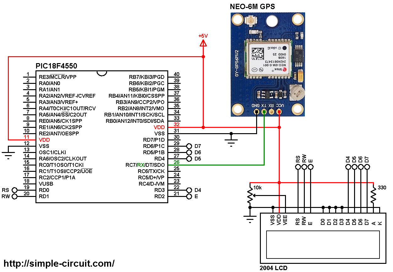
(All grounded terminal are connected together)
The NEO-6M GPS module board has 4 pins connected as follows:
GND (Ground) pin connected to circuit GND
TX pin goes to PIC18F4550 RX (RC7) pin (pin #26)
RX pin is not connected (there is no need to send data from the microcontroller to the GPS module)
VCC pin goes to circuit +5V pin.
The 20×4 LCD screen is used to display the real time clock time and date where:
RS —> RD0 pin
RW —> RD1 pin
E —> RD2pin
D4 —> RD3 pin
D5 —> RD4 pin
D6 —> RD5 pin
D7 —> RD6 pin
VSS, D0, D1, D2, D3 and K are connected to circuit GND (ground)
VEE to the variable resistor (or potentiometer) output pin
VDD to +5V and A to +5V through 330 ohm resistor
VEE pin is used to control the contrast of the LCD. A (anode) and K (cathode) are the back light LED pins.
In this project the PIC18F4550 microcontroller runs with its internal oscillator @ 8 MHz, MCLR pin is configured as an input pin.
GPS Real time clock using PIC18F4550 and NEO-6M module C code:
The following C code is for CCS C compiler, it was tested with version 5.051.
In this project I used a small GPS library, this library decodes NMEA sentence that the microcontroller receive from the GPS module, therefore getting time and date is more easier.
GPS Library for CCS C compiler downloaded link is the one below, library full name is “GPS_Lib.c“:
GPS Library download
after the download, add the library file (GPS_Lib.c) to project folder or CCS C compiler drivers folder.
As known the GPS module always gives a UTC time and date which may need to be converted to our time zone (for example UTC + 1). To do the conversion of time we can use CCS C time library (built-in library), time library files are time.h and time.c which are located in CCS C drivers folder.
To be able to convert the UTC standard time into our time zone, first we’ve to convert that time (UTC) into UNIX time (also known UNIX Epoch time or POSIX time ) which is the number of seconds that have elapsed since 00:00:00 UTC, 1 January 1970.
After we get the UNIX Epoch time we add our time offset to it (plus or minus), for example for UTC + 1 time zone we add 3600 seconds, for UTC – 5 we add -18000 seconds and so on.
After that we converter the ‘new’ UNIX time into our zone time and date.
Functions used in the code:
kbhit(): returns 1 if a character has been received by the MCU.
GPS library functions:
GPSRead(): returns 1 if the GPS data (NMEA sentences) have been received and parsed with successful.
GPSHour(): returns hours from the decoded GPS data (0 – 23)
GPSMinute(): returns minutes (0 – 59)
GPSSecond(): returns seconds (0 – 59)
GPSDay(): returns day of month (1 – 31)
GPSMonth(): returns month (1 – 12)
GPSYear(): returns year, ones and tens (0 – 99)
CCS C Time library functions:
First we need to save the UTC time and date (in order to convert it to UNIX time) to a variable of type struct_tm (structure type), I named this variable as: utc_time. This variable is a collection of 8 variables, 6 of them are required:
utc_time.tm_hour, utc_time.tm_min, utc_time.tm_sec, utc_time.tm_mday, utc_time.tm_mon and utc_time.tm_year.
utc_time.tm_mon has to be between 0 and 11. utc_time.tm_year is number of years starting from 1900 (for example 118 for 2018).
Now we can convert the UTC time to UNIX time with the following function where the converted UNIX time is saved to unix_time variable of type time_t (signed int32):
unix_time = mktime(&utc_time);
Returning from the UNIX time to our zone time and date is also simple, here an other variable of type struct_tm is used, I used a variable named: my_time. This variable is also a collection of 8 variables, 7 of them are used:
my_time->tm_hour, my_time->tm_min, my_time->tm_sec, my_time->tm_mday, my_time->tm_mon, my_time->tm_year and my_time->tm_wday.
The last variable is day of week between 0 and 6 (0 for Sunday).
tm_mday is day of month (1-31)
tm_mon is the month (0-11)
Our zone time and date are stored to the variable my_time using the function:
my_time = localtime(&unix_time);
CCS C code:
1 2 3 4 5 6 7 8 9 10 11 12 13 14 15 16 17 18 19 20 21 22 23 24 25 26 27 28 29 30 31 32 33 34 35 36 37 38 39 40 41 42 43 44 45 46 47 48 49 50 51 52 53 54 55 56 57 58 59 60 61 62 63 64 65 66 67 68 69 70 71 72 73 74 75 76 77 78 79 80 81 82 83 84 85 86 87 88 89 90 91 92 93 94 95 96 97 98 99 100 101 102 103 104 105 106 107 108 109 110 111 112 113 114 115 116 117 118 119 120 121 122 123 124 125 126 | /************************************************************************************** GPS real time clock using PIC18F4550 and NEO-6M GPS module C Code for CCS C compiler Internal oscillator used @ 8MHz This is a free software with NO WARRANTY. http://simple-circuit.com/ ***************************************************************************************/ #define time_offset 3600 // define a clock offset of 3600 seconds (1 hour) ==> UTC + 1 //LCD module connections #define LCD_RS_PIN PIN_D0 #define LCD_RW_PIN PIN_D1 #define LCD_ENABLE_PIN PIN_D2 #define LCD_DATA4 PIN_D3 #define LCD_DATA5 PIN_D4 #define LCD_DATA6 PIN_D5 #define LCD_DATA7 PIN_D6 //End LCD module connections #include <18F4550.h> #device PASS_STRINGS = IN_RAM #fuses NOMCLR, INTRC_IO, NOWDT, NOPROTECT, NOLVP #use delay(clock = 8MHz) #use fast_io(D) #use RS232(UART1, BAUD = 9600, ERRORS) // UART configuration & initialization // include CCS C LCD library #include <lcd.c> // include GPS library source file (GPS_Lib.c) #include <GPS_Lib.c> // include CCS C time library #include <time.h> #include <time.c> // CCS C time library variables time_t unix_time; struct_tm utc_time, *my_time; // other variables char time_c[] = "TIME: : : "; char date_c[] = "DATE: - -20 "; void print_wday(int8 wday) { lcd_gotoxy(6, 2); switch(wday) { case 0: lcd_putc(" SUNDAY "); break; case 1: lcd_putc(" MONDAY "); break; case 2: lcd_putc(" TUESDAY "); break; case 3: lcd_putc("WEDNESDAY"); break; case 4: lcd_putc("THURSDAY "); break; case 5: lcd_putc(" FRIDAY "); break; default: lcd_putc("SATURDAY "); } } // main function void main(void) { setup_oscillator(OSC_8MHZ); // Set internal oscillator to 8MHz lcd_init(); // initialize LCD module lcd_gotoxy(2, 1); // go to column 2, row 1 lcd_putc("GPS CLOCK (UTC+1)"); while(TRUE) { if(kbhit()) { if(GPSRead()) { // read UTC time and date and save them to utc_time structure utc_time.tm_hour = GPSHour(); utc_time.tm_min = GPSMinute(); utc_time.tm_sec = GPSSecond(); // adjust values to be time.h compatible utc_time.tm_mday = GPSDay(); // month day 1-31 utc_time.tm_mon = GPSMonth() - 1; // month 0-11 utc_time.tm_year = GPSYear() + 100; // year starting at 1900 // get unix time unix_time = mktime(&utc_time); // add the offset (in seconds) to the unix time unix_time += time_offset; // get the local time my_time = localtime(&unix_time); time_c[6] = my_time->tm_hour / 10 + '0'; time_c[7] = my_time->tm_hour % 10 + '0'; time_c[9] = my_time->tm_min / 10 + '0'; time_c[10] = my_time->tm_min % 10 + '0'; time_c[12] = my_time->tm_sec / 10 + '0'; time_c[13] = my_time->tm_sec % 10 + '0'; date_c[6] = my_time->tm_mday / 10 + '0'; date_c[7] = my_time->tm_mday % 10 + '0'; date_c[9] = (my_time->tm_mon + 1) / 10 + '0'; date_c[10] = (my_time->tm_mon + 1) % 10 + '0'; date_c[14] = (my_time->tm_year / 10) % 10 + '0'; date_c[15] = my_time->tm_year % 10 + '0'; // print time & date print_wday(my_time->tm_wday); // print day of the week lcd_gotoxy(23, 1); // go to column 3 row 3 printf(lcd_putc, time_c); // print time (HH:MM:SS) lcd_gotoxy(23, 2); // go to column 3 row 4 printf(lcd_putc, date_c); // print date (DD-MM-YYYY) } } } } // End of code. |
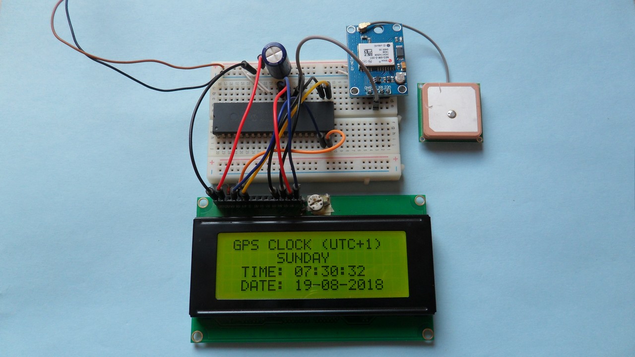
The result of this project should be as shown in the following video where PIC16F877A is used:


