This topic shows how to build an infrared remote control transmitter and receiver using PIC18F4550 microcontroller and CCS PIC C compiler.
The IR system has two circuits: transmitter circuit and receiver circuit. Both circuits have the same microcontroller type which is PIC18F4550.
This system uses RC5 protocol from Philips. The following link shows how to decode RC5 IR remote control:
RC-5 remote control decoder with PIC18F4550 and CCS C
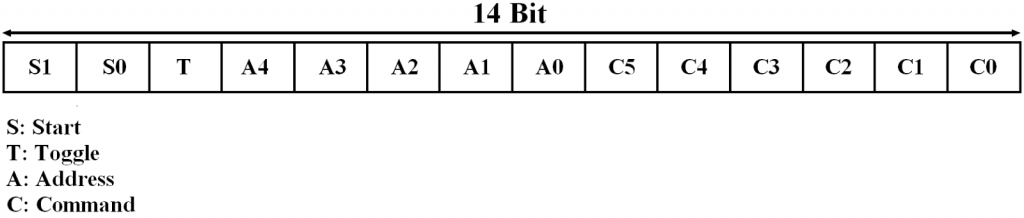
The RC5 protocol message is 14-bit data length which are 2 start bits, 1 toggle bit, 5 address bits and 6 command bits as shown in the following figure. The most important are the address and command bits.
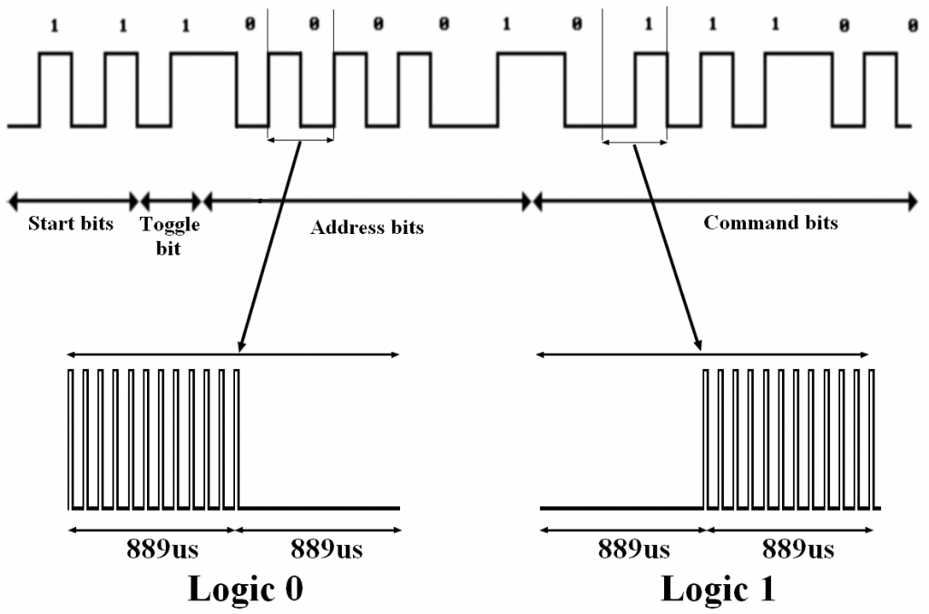
The IR signal needs a carrier frequency and the carrier frequency of the RC5 protocol is 36KHz with a duty cycle of 25% to 33%.
The following figure shows a complete RC5 code with a simple example:
IR RC-5 remote control transmitter circuit (RC-5 Encoder):
The following image shows the transmitter circuit schematic of the IR system.
There are five push buttons in the circuit, each push button sends a different IR code via an IR transmitter.
PIC18F4550 internal oscillator is used (8MHz) and MCLR is disabled.
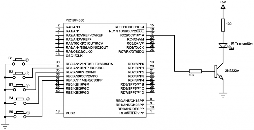
The PIC18F4550 MCU needs 5V supply on its VDD and VSS pins. Its internal oscillator is used and MCLR pin function is disabled.
IR RC5 remote control transmitter circuit using PIC18F4550 CCS C code:
To get a carrier frequency of 36KHz, PIC18F4550 PWM1 module is used with 25% duty cycle.
Logic 0 code with carrier frequency:
pwm_on();
delay_us(889);
pwm_off();
delay_us(889);
And logic 1 code with carrier frequency:
pwm_off();
delay_us(889);
pwm_on();
delay_us(889);
In the circuit there are five pushbuttons: B1, B2, B3, B4 and B5, they send the following address and command codes:
B1: address = 0 and command = 0,
B2: address = 0 and command = 1,
B3: address = 0 and command = 2,
B4: address = 0 and command = 3,
B5: address = 0 and command = 4.
The two start bits are always 1’s and the toggle bit might be 1 or 0.
The following C code is the full code for this circuit and it was tested with CCS PIC C compiler version 5.0.51.
1 2 3 4 5 6 7 8 9 10 11 12 13 14 15 16 17 18 19 20 21 22 23 24 25 26 27 28 29 30 31 32 33 34 35 36 37 38 39 40 41 42 43 44 45 46 47 48 49 50 51 52 53 54 55 56 57 58 59 60 61 62 63 64 65 66 67 68 69 70 71 72 73 74 75 76 77 78 79 80 81 82 83 84 85 86 | // PIC18F4550 IR RC5 encoder CCS PIC C compiler code // http://ccspicc.blogspot.com/ #include <18F4550.h> #fuses NOMCLR INTRC_IO #use delay(clock = 8000000) #use pwm (PWM1, FREQUENCY = 36KHz, DUTY = 25, PWM_OFF) short toggle; void send_ir_signal(int8 address, int8 command){ int8 i = 0; // Start bits pwm_on(); delay_us(889); pwm_off(); delay_us(889); pwm_on(); delay_us(889); pwm_off(); // Toggle bit toggle = !toggle; if(toggle){ delay_us(889); pwm_on(); delay_us(889); } else { pwm_on(); delay_us(889); pwm_off(); delay_us(889); } // Address for(i = 0x10; i > 0; i = i >> 1){ if( address & i ){ pwm_off(); delay_us(889); pwm_on(); delay_us(889);} else { pwm_on(); delay_us(889); pwm_off(); delay_us(889);} } // Command for (i = 0x20; i > 0; i = i >> 1){ if ( command & i ){ pwm_off(); delay_us(889); pwm_on(); delay_us(889);} else { pwm_on(); delay_us(889); pwm_off(); delay_us(889);} } pwm_off(); } void main(){ setup_oscillator(OSC_8MHZ); // Set internal oscillator to 8MHz setup_adc_ports(NO_ANALOGS); // Configure AN0 and AN1 as analog inputs port_b_pullups(TRUE); output_b(0); set_tris_b(0x1F); delay_ms(100); // Wait 100ms while(TRUE){ if(!input(PIN_B0)){ send_ir_signal(0, 0); delay_ms(500);} if(!input(PIN_B1)){ send_ir_signal(0, 1); delay_ms(500);} if(!input(PIN_B2)){ send_ir_signal(0, 2); delay_ms(500);} if(!input(PIN_B3)){ send_ir_signal(0, 3); delay_ms(500);} if(!input(PIN_B4)){ send_ir_signal(0, 4); delay_ms(500);} } } |
IR RC-5 remote control transmitter circuit (RC-5 Decoder):
The RC5 IR receiver circuit schematic (RC5 decode) is shown below:
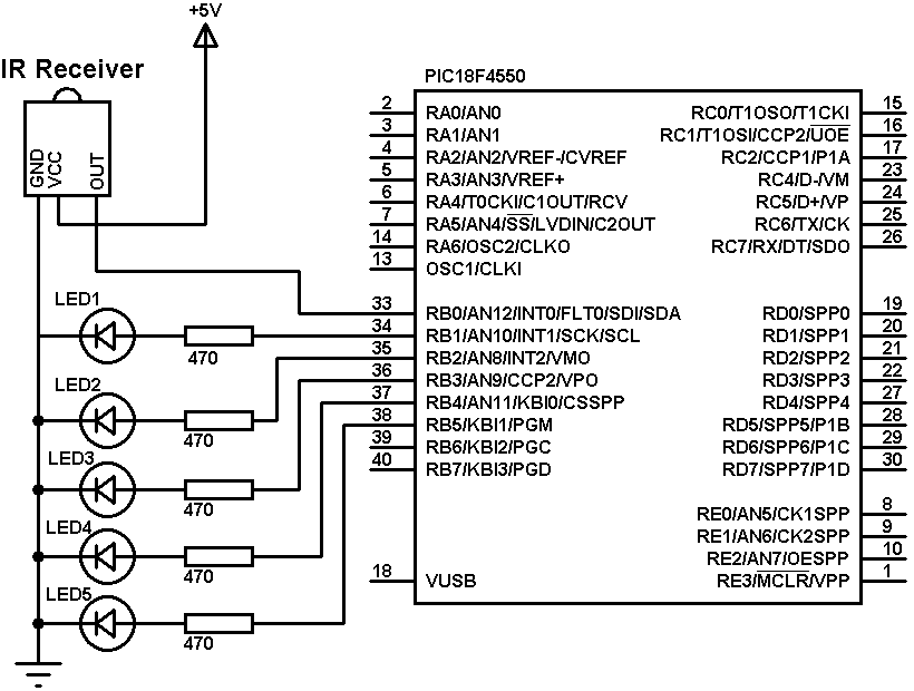 PIC18F4550 internal oscillator is used (8MHz) and MCLR is disabled. It needs +5V on its VDD – VSS pins.
In the receiver circuit there are 5 LEDs, each LED is controlled by one pushbutton on the transmitter circuit. The IR receiver receives IR signals transmitted from the IR transmitter on the transmitter circuit.
IR RC5 remote control receiver circuit using PIC18F4550 CCS C code:
The microcontroller waits until an IR signal is received (RB0 pin goes from high to low). After an IR signal is received the microcontroller checks if the received signal uses RC5 protocol, if so the microcontroller starts decoding the RC5 signal and the most important are the address bits and the command bits.
If address = 0 and command = 0: toggle LED1
If address = 0 and command = 1: toggle LED2
If address = 0 and command = 2: toggle LED3
If address = 0 and command = 3: toggle LED4
If address = 0 and command = 4: toggle LED5
The following C code is the full code for the receiver microcontroller:
1 2 3 4 5 6 7 8 9 10 11 12 13 14 15 16 17 18 19 20 21 22 23 24 25 26 27 28 29 30 31 32 33 34 35 36 37 38 39 40 41 42 43 44 45 46 47 48 49 50 51 52 53 54 55 56 57 58 59 60 61 62 63 64 65 66 67 68 69 70 71 72 | // RC5 IR receiver(decoder) with PIC18F4550 CCS PIC C compiler code // http://ccspicc.blogspot.com/ #include <18F4550.h> #fuses NOMCLR INTRC_IO #use delay(clock = 8000000) #use fast_io(B) int1 toggle; unsigned int8 count, i, address, command; short remote_read(){ count = 0; // Check if the received signal uses RC5 protocol while((input(PIN_B0) == 0) && (count < 20)){ count++; delay_us(50);} if( (count > 20) || (count < 14)) // Signal doesn't use RC5 protocol return FALSE; // Return count = 0; while((input(PIN_B0)) && (count < 20)){ count++; delay_us(50);} if( (count > 20) || (count < 14)) // Signal doesn't use RC5 protocol return FALSE ; // Return count = 0; while((input(PIN_B0) == 0) && (count < 40)){ count++; delay_us(50);} if( (count > 40) || (count < 14)) // Signal doesn't use RC5 protocol return FALSE ; // Return // End check (The received signal uses RC5 protocol) if(count > 30) delay_us(400); else delay_us(1300); for(i = 0; i < 12; i++){ if(i == 0){ if(input(PIN_B0) == 1) toggle = 0; else toggle = 1; } else { if(i < 6){ //Read address bits if(input(PIN_B0) == 1) bit_clear(address, (5 - i)); //Clear bit (5-i) else bit_set(address, (5 - i)); //Set bit (5-i) } else { //Read command bits if(input(PIN_B0) == 1) bit_clear(command, (11 - i)); //Clear bit (11-i) else bit_set(command, (11 - i)); //Set bit (11-i) } } delay_us(1778); } address &= 0x1F; command &= 0x3F; return TRUE; } void main(){ setup_oscillator(OSC_8MHZ); // Set internal oscillator to 8MHz setup_adc_ports(NO_ANALOGS); // Configure AN pins as digital output_b(0); // PORTB initial state set_tris_b(1); // Configure RB0 pin as input delay_ms(100); // Wait 100ms while(TRUE){ while(input(PIN_B0)); // Wait until RB0 pin falls if(remote_read()){ if((address == 0) && (command == 0)) output_toggle(PIN_B1); if((address == 0) && (command == 1)) output_toggle(PIN_B2); if((address == 0) && (command == 2)) output_toggle(PIN_B3); if((address == 0) && (command == 3)) output_toggle(PIN_B4); if((address == 0) && (command == 4)) output_toggle(PIN_B5); } delay_ms(10); } } |
IR remote control system based on PIC microcontroller video:
The following video shows a hardware circuits for the project.


#use pwm (PWM1, FREQUENCY = 36000Hz, DUTY = 25, PWM_OFF)
“Error 44” Line 8