The following topic shows how to control speed and direct of a DC motor using PIC18F4550 and H-bridge circuit:
DC motor speed and direction control with PIC18F4550 microcontroller
DC motor control with PIC18F4550 and L293D circuit:
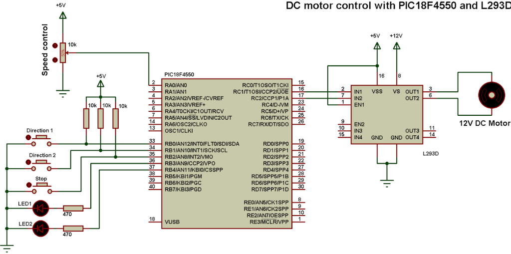
In the circuit there are 3 push buttons, 2 for selecting the direction and the other one for stopping the motor. The 2 LEDs are used to indicate the motor rotation direction, if LED1 is ON that means direction 1 has been chosen and the same thing for LED 2. If both LEDs are OFF that means the motor has been stopped.
The nominal voltage of the motor is 12V as well as L293D VS input voltage. The L293D VS voltage should be the same as the DC motor voltage and L293D VSS voltage is +5V.
A pot (pin AN0) is used to change the motor speed.
The microcontroller PIC18F4550 reads analog data from channel 0 and use the digital value to set the PWM duty cycle. If direction 1 button is pressed the microcontroller starts PWM1 (RC2 pin) and stops PWM2 (RC1 pin) and if direction 2 button is pressed the microcontroller stops PWM1 (RC2 pin) and starts PWM2 (RC1 pin), when the stop button is pressed the microcontroller stops PWM1 and PWM2 signals and the motor will stop.
The PWM (PWM1 & 2) frequency is 488Hz.
DC motor control with PIC18F4550 and L293D CCS PIC C code:
PIC18F4550 Timer2 is configured to generate a PWM frequency of 488Hz and the microcontroller runs with 8MHz internal oscillator.
The microcontroller PIC18F4550 reads RA0 analog value and stores the digital value on variable (i), this variable is used to set duty cycle of the active PWM (PWM1 or PWM2).
1 2 3 4 5 6 7 8 9 10 11 12 13 14 15 16 17 18 19 20 21 22 23 24 25 26 27 28 29 30 31 32 33 34 35 36 37 38 39 40 41 42 43 44 45 46 47 48 49 50 51 52 53 54 55 56 57 | // Dc motor control with PIC18F4550 and L293D CCS C code #include <18F4550.h> #device ADC = 10 #fuses NOMCLR INTRC_IO #use delay(clock = 8000000) #use fast_io(B) #use fast_io(C) unsigned int16 i ; void main(){ setup_oscillator(OSC_8MHZ); // Set internal oscillator to 8MHz output_b(0); // PORTB initial state set_tris_b(7); // Configure RB0, RB1 & RB2 as inputs output_c(0); // PORTC initial state set_tris_c(0); // Configure PORTC pins as outputs output_d(0); // PORTD initial state set_tris_d(0); // Configure PORTD pins as outputs setup_adc(ADC_CLOCK_DIV_8); // Set ADC conversion time to 8Tosc setup_adc_ports(AN0); // Configure AN0 as analog input set_adc_channel(0); // Select channel AN0 setup_timer_2(T2_DIV_BY_16, 255, 1); // Set PWM frequency to 500Hz delay_ms(100); // Wait 100ms while(TRUE){ i = read_adc(); // Read from AN0 and store in i if(input(PIN_B3) == 1) // If direction 1 is selected set_pwm1_duty(i); // Set pwm1 duty cycle if(input(PIN_B4) == 1) // If direction 2 is selected set_pwm2_duty(i); // Set pwm2 duty cycle delay_ms(10); // Wait 10ms if(input(PIN_B0) == 0){ // If RB0 button pressed if(input(PIN_B3) == 0){ // If direction 1 not already selected output_b(0); // Both LEDs OFF setup_ccp1(CCP_OFF); // CCP1 OFF setup_ccp2(CCP_OFF); // CCP2 OFF output_c(0); // PORTC pins low delay_ms(100); // Wait 100ms setup_ccp1(CCP_PWM); // Configure CCP1 as a PWM output_high(PIN_B3); // RB3 LED ON }} if(input(PIN_B1) == 0){ // If RB1 button pressed if(input(PIN_B4) == 0){ // If direction 2 not already selected output_b(0); // Both LEDs OFF setup_ccp1(CCP_OFF); // CCP1 OFF setup_ccp2(CCP_OFF); // CCP2 OFF output_c(0); // PORTC pins low delay_ms(100); // Wait 100ms setup_ccp2(CCP_PWM); // Configure CCP2 as a PWM output_high(PIN_B4); // RB4 LED ON }} if(input(PIN_B2) == 0){ // If RB2 button pressed setup_ccp1(CCP_OFF); // CCP1 OFF setup_ccp2(CCP_OFF); // CCP2 OFF output_c(0); // PORTC pins low output_b(0);} // Both LEDs OFF } } |
DC motor control with PIC18F4550 and L293D Proteus simulation video:
The following video shows the simulation using Proteus.
Proteus simulation file download:
You can download Proteus simulation file from the following link.
DOWNLOAD


hey bro.proteus simulation file link is empty.could you upload the simulation file again? i will be thanks.
Could you please be programming in assembly language? Thank you
Good day all,
Would it be possible to have a copy of the HEX file for the above project as I’m starting out in controller programming and it would be useful for diagnosing the mistakes that I keep making, which is many.
With thanks