This is another project that shows how to interface PIC18F4550 microcontroller with Nokia 5110 (Nokia 3310) LCD and how to use its library.
In this project the Nokia 5110 LCD (84 x 48 pixel) is used to display temperature (in degree Celsius) and humidity (in relative humidity percent, rH%) where DHT22 (equivalent to AM2302) digital humidity and temperature sensor is used.
The compiler used in this project is CCS PIC C.
To see how to interface the PIC18F4550 with the Nokia 5110 for the first time, visit the post below:
Interfacing PIC18F4550 MCU with NOKIA 5110 LCD
and to see how to interface the PIC18F4550 MCU with the DHT22 sensor, take a look at this post:
PIC18F4550 Interface with DHT22(AM2302) sensor + Proteus simulation
Hardware Required:
- PIC18F4550 microcontroller
- Nokia 5110 (3310) LCD module
- DHT22 (AM2302) humidity and temperature sensor —-> datasheet
- AMS1117 3V3 voltage regulator
- 10 uF capacitor
- 100 nF ceramic capacitor
- 5 x 3.3k ohm resistor
- 5 x 2.2k ohm resistor
- 4.7k ohm resistor
- 5V source
- Breadboard
- Jumper wires
PIC18F4550 with Nokia 5110 LCD and DHT22 sensor circuit:
The following image shows project circuit diagram.
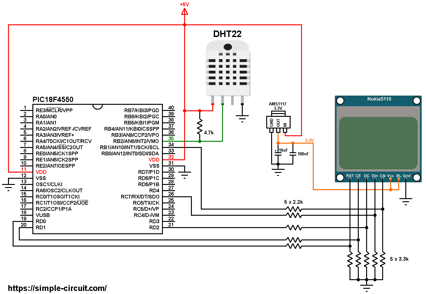
All the grounded terminals are connected together.
The DHT22 sensor has 4 pins (from left to right):
VCC: connected to circuit +5V
data pin: connected to PIC18F4550 pin RB2 (#35)
not connected pin
GND: connected to circuit ground (0V).
The Nokia 5110 which is shown in the circuit diagram has 8 pins (from left to right): RST (reset), CE (chip enable), DC (or D/C: data/command), Din (data in), Clk (clock), VCC (3.3V), BL (back light) and Gnd (ground).
The Nokia 5110 LCD works with 3.3V only (power supply and control lines). The LCD module is supplied with 3.3V which comes from the AMS1117 3V3 voltage regulator, this regulator steps down the 5V into 3.3V.
To connect the PIC18F4550 to the LCD module, I used voltage divider for each line which means there are 5 voltage dividers. Each voltage divider consists of 2.2k and 3.3k resistors, this drops the 5V into 3V which is sufficient.
Therefore, the Nokia 5110 LCD pins are connected to PIC18F4550 MCU as follows (each one through voltage divider):
RST (reset) pin is connected to pin RD0 (#19)
CE (chip enable) pin is connected to pin RD1 (#20)
DC (data/command) pin is connected to pin RD2 (#21)
DIN (data in) pin is connected to pin RC7 (#26)
CLK (clock) pin is connected to pin RB1 (#34)
VCC and BL are connected to AMS1117 3V3 regulator output pin and GND is connected to circuit ground (0V).
In this project the PIC18F4550 uses its internal oscillator and MCLR pin function is disabled.
Interfacing PIC18F4550 with DHT11 sensor Nokia 5110 LCD C code:
The C code below is for CCS C compiler, it was tested with version 5.051.
To be able to compile project C code, a driver for the Nokia 5110 LCD is required, download link is below. After you download the driver file which named NOKIA5110.c, add it to your project folder:
Nokia 5110 LCD driver for CCS C compiler
Connection of LCD reset, chip select and data/command pin are defined in the code as:
1 2 3 4 | // define LCD module pin connections #define LCD_RST PIN_D0 // reset pin, optional! #define LCD_CS PIN_D1 // chip select pin, optional! #define LCD_DC PIN_D2 // data/command pin |
And the DHT22 data pin is defined as:
1 2 | // define DHT22 sensor data pin connection #define DHT22_PIN PIN_B2 |
Rest of code is described through comments!
Full CCS C code:
1 2 3 4 5 6 7 8 9 10 11 12 13 14 15 16 17 18 19 20 21 22 23 24 25 26 27 28 29 30 31 32 33 34 35 36 37 38 39 40 41 42 43 44 45 46 47 48 49 50 51 52 53 54 55 56 57 58 59 60 61 62 63 64 65 66 67 68 69 70 71 72 73 74 75 76 77 78 79 80 81 82 83 84 85 86 87 88 89 90 91 92 93 94 95 96 97 98 99 100 101 102 103 104 105 106 107 108 109 110 111 112 113 114 115 116 117 118 119 120 121 122 123 124 125 126 127 128 129 130 131 132 133 134 135 136 137 138 139 140 141 142 143 144 145 146 147 148 149 150 151 152 153 154 155 156 157 158 159 160 161 162 163 164 165 166 167 168 169 170 171 172 173 174 175 176 177 178 179 180 181 182 183 184 185 | /* * Interfacing PIC18F4550 microcontroller with Nokia 5110 LCD * and DHT22 sensor. * C Code for CCS C compiler. * This is a free software with NO WARRANTY. * http://simple-circuit.com/ */ // define LCD module pin connections #define LCD_RST PIN_D0 // reset pin, optional! #define LCD_CS PIN_D1 // chip select pin, optional! #define LCD_DC PIN_D2 // data/command pin // define DHT22 sensor data pin connection #define DHT22_PIN PIN_B2 #include <18F4550.h> #fuses NOMCLR, INTRC_IO, NOWDT, NOPROTECT, NOLVP #use delay(clock = 8MHz) #use spi(SPI1, BAUD = 1000000, MODE = 3, BITS = 8, STREAM = LCD_STREAM) #include <NOKIA5110.c> // include Nokia 5110 LCD driver source file int8 T_Byte1, T_Byte2, RH_Byte1, RH_Byte2, CheckSum; int16 Temp, RH; // send start signal to the sensor void Start_Signal(void) { output_drive(DHT22_PIN); // configure connection pin as output output_low(DHT22_PIN); // connection pin output low delay_ms(25); // wait 25 ms output_high(DHT22_PIN); // connection pin output high delay_us(30); // wait 30 us output_float(DHT22_PIN); // configure connection pin as input } // check sensor response int1 Check_Response(void) { setup_timer_1(T1_INTERNAL | T1_DIV_BY_2); // start Timer1 set_timer1(0); // set Timer1 value to 0 while(!input(DHT22_PIN) && get_timer1() < 100); // wait until DHT22_PIN becomes high (cheking of 80µs low time response) if(get_timer1() >= 100) // if response time >= 100µS ==> response error return 0; // return 0 (device has a problem with response) else { set_timer1(0); // set Timer1 value to 0 while(input(DHT22_PIN) && get_timer1() < 100); // wait until DHT22_PIN becomes low (cheking of 80µs high time response) if(get_timer1() >= 100) // if response time >= 100µS ==> response error return 0; // return 0 (device has a problem with response) else return 1; // return 1 (response OK) } } // data read function void Read_Data(int8 *dht_data) { int8 j; *dht_data = 0; setup_timer_1(T1_INTERNAL | T1_DIV_BY_2); // start Timer1 for(j = 0; j < 8; j++) { set_timer1(0); // reset Timer1 while(!input(DHT22_PIN)) // wait until DHT22_PIN becomes high if(get_timer1() >= 100) // if low time >= 100µs ==> Time out error (normally it takes 50µs) { setup_timer_1(T1_DISABLED); // disable Timer1 return ; } set_timer1(0); // reset Timer1 while(input(DHT22_PIN)) // wait until DHT22_PIN becomes low if(get_timer1() > 100) // if high time > 100µs ==> Time out error (normally it takes 26-28µs for 0 and 70µs for 1) { setup_timer_1(T1_DISABLED); // disable Timer1 return ; // return (timeout error) } if(get_timer1() > 50) // if high time > 50µS ==> sensor sent 1 bit_set(*dht_data, (7 - j)); // set bit (7 - j) } setup_timer_1(T1_DISABLED); // disable Timer1 } // main function void main() { setup_oscillator(OSC_8MHZ); // set internal oscillator to 8MHz delay_ms(1000); // wait 1 second LCD_Begin(); // initialize the LCD LCD_Clear(); // clear the buffer LCD_SetContrast(50); // set LCD contrast LCD_DrawHLine(0, 23, LCDWIDTH); // draw horizontal line LCD_TextSize(1); // set text size to 1 LCD_GotoXY(6, 0); // move cursor to position (6, 0) pixel LCD_Print("TEMPERATURE:"); LCD_GotoXY(15, 28); // move cursor to position (15, 28) pixel LCD_Print("HUMIDITY:"); LCD_Display(); while(TRUE) { Start_Signal(); // Send a start signal to the sensor if(Check_Response()) // check if there is a response from sensor (if OK start reading humidity and temperature data) { // response OK ==> read (and save) data from the DHT22 sensor Read_Data(&RH_Byte1); // read humidity 1st byte Read_Data(&RH_Byte2); // read humidity 2nd byte Read_Data(&T_Byte1); // read temperature 1st byte Read_Data(&T_Byte2); // read temperature 2nd byte Read_Data(&CheckSum); // read checksum // test if all data were sent correctly if(CheckSum == ((RH_Byte1 + RH_Byte2 + T_Byte1 + T_Byte2) & 0xFF)) { // prepare & print temperature Temp = T_Byte1; Temp = (Temp << 8) | T_Byte2; LCD_GotoXY(18, 12); if(Temp & 0x8000) { LCD_Print('-'); Temp = Temp & 0x7FFF; } else LCD_Print(' '); printf(LCD_Print, "%02Lu.%Lu C", Temp / 10, Temp % 10); LCD_DrawRect(50, 12, 3, 3); // print degree symbol ( ° ) // prepare & print humidity RH = RH_Byte1; RH = (RH << 8) | RH_Byte2; LCD_GotoXY(18, 40); if( RH >= 1000) { LCD_Print('1'); RH = 0; } else LCD_Print(' '); printf(LCD_Print, "%02Lu.%Lu %%", RH / 10, RH % 10); } // checksum error else { LCD_GotoXY(18, 12); LCD_Print(" ChkSum"); LCD_GotoXY(18, 40); LCD_Print(" Error!"); } } // sensor response error (connection error) else { setup_timer_1(T1_DISABLED); // disable Timer1 LCD_GotoXY(18, 12); LCD_Print(" Sensor"); LCD_GotoXY(18, 40); LCD_Print(" Error!"); } LCD_Display(); // print display buffer delay_ms(1000); // wait 1 second between readings } } // end of code. |
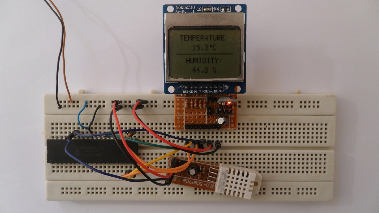
My simple protoboard circuit gave the following result:
Proteus simulation of this project should give the same result as shown in the following video where Arduino UNO is used instead of the PIC18F4550 microcontroller:


