PIC18F4550 PWM + ADC Example
PIC18F4550 has one CCP module and one ECCP (Enhanced CCP) module, the CCP module which CCP2 can generate a PWM signal on pin RC1, and ECCP which is CCP1 has an enhanced PWM capabilities, but this ECCP can work as a simple CCP. In this topic we are going to see how to use CCP1 (not enhanced CCP) and CCP2 to generate PWM signals on RC2 and RC1 respectively.
First we have to configure the CCP module to run as a PWM using the following CCS commands:
setup_ccp1(CCP_PWM); // Configure CCP1 as a PWM
setup_ccp2(CCP_PWM); // Configure CCP2 as a PWM
Then we have to use Timer2 to setup the pwm frequency.
Use the following equation to compute the pwm frequency:
PWM period = [(PR2) + 1] • 4 • Tosc • (TMR2 Prescale Value)
Where PWM frequency is defined as 1/[PWM period].
PR2 is Timer2 preload value,
Tosc = 1/(MCU_frequency)
TMR2 Prescale Value can be 1, 4 or 16.
For example forPR2 = 250 , microcontroller frequency = 8MHz and Prescale = 16 we get a PWM frequency of 500Hz.
The CCS Timer2 configuration has the following form:
setup_timer_2(mode, period, postscale);
where: mode is TMR2 Prescale Value, period is PR2 and postscaler is not used in the determination of the PWM frequency (keep it 1).
Previous example gives the following Timer2 configuration command:
setup_timer_2(T2_DIV_BY_16, 250, 1);
The last CCS command is the PWM duty cycle command:
set_pwm1_duty(value);
PIC18F4550 PWM +ADC example:
This example shows how to use the digital value of the analog reading to set the duty cycle of the PWM signal. This example uses two analog channels AN0 and AN1 and the two CCP modules CCP1 and CCP2 to control the brightness of two LEDs connected to RC2 (CCP1 output) and RC1 (CCP2 output) as shown in the following circuit schematic:
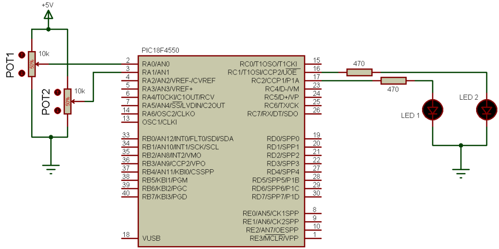
Two pots are used to control the brightness of the LEDs. The microcontroller PIC18F4550 runs with its internal oscillator at 8MHz. If the frequency of the oscillator changed, the PWM frequency will also change.
To see how to use PIC18F4550 ADC module see the following topic:
PIC18F4550 ADC example with CCS PIC C compiler
PIC18F4550 PWM + ADC example CCS C code:
The resolution of the PWM signal is approximately 10 bits (9.96 bits).
1 2 3 4 5 6 7 8 9 10 11 12 13 14 15 16 17 18 19 20 21 22 23 24 25 26 27 28 29 30 | // PIC18F4550 ADC + PWM CCS C code (10-bit PWM resolution) #include <18F4550.h> #device ADC = 10 #fuses NOMCLR INTRC_IO #use delay(clock = 8000000) unsigned int16 i, j; void main(){ setup_oscillator(OSC_8MHZ); // Set internal oscillator to 8MHz setup_adc(ADC_CLOCK_DIV_8); // Set ADC conversion time to 8Tosc setup_adc_ports(AN0_TO_AN1); // Configure AN0 and AN1 as analog inputs setup_ccp1(CCP_PWM); // Configure CCP1 as a PWM setup_ccp2(CCP_PWM); // Configure CCP2 as a PWM setup_timer_2(T2_DIV_BY_16, 250, 1); // Set PWM frequency to 500Hz delay_ms(100); // Wait 100ms while(TRUE){ set_adc_channel(0); // Select channel AN0 delay_ms(1); // Wait 1ms i = read_adc(); // Read from AN0 and store in i delay_ms(1); // Wait 1ms set_adc_channel(1); // Select channel AN1 delay_ms(1); // Wait 1ms j = read_adc(); // Read from AN1 and store in j set_pwm1_duty(i); // Set pwm1 duty cycle to i set_pwm2_duty(j); // Set pwm2 duty cycle to j delay_ms(1); // Wait 1ms } } |
PIC18F4550 PWM + ADC video:
The following video shows a real hardware circuit of the previous example.


