This post shows how to build a weather station using PIC18F46K22 microcontroller and BME280 barometric pressure, temperature and humidity sensor.
The PIC18F46K22 MCU reads temperature & humidity & pressure values from the BME280 sensor and print them (respectively in °C & RH% & hPa) on SSD1306 OLED display (128×64 pixel).
MikroC PRO for PIC compiler is used in this project.
In this project the SSD1306 OLED is configured to work in I2C mode, make sure that your display is configured to work in I2C mode, some displays need jumper placing or some soldering.
To see how to interface PIC18F46K22 MCU with SSD1306 OLED display (I2C mode), visit this topic:
Interfacing PIC18F46K22 with SSD1306 OLED display | mikroC Projects
and to see how to interface PIC microcontroller with BME280 sensor using mikroC PRO for PIC compiler, take a look at this project:
PIC MCU with BME280 pressure, temperature and humidity sensor | mikroC Projects
Hardware Required:
- PIC18F46K22 microcontroller —-> datasheet
- SSD1306 OLED display
- BME280 sensor module (with built-in 3.3V regulator and level shifter) —-> BME280 datasheet
- 5V source
- Breadboard
- Jumper wires
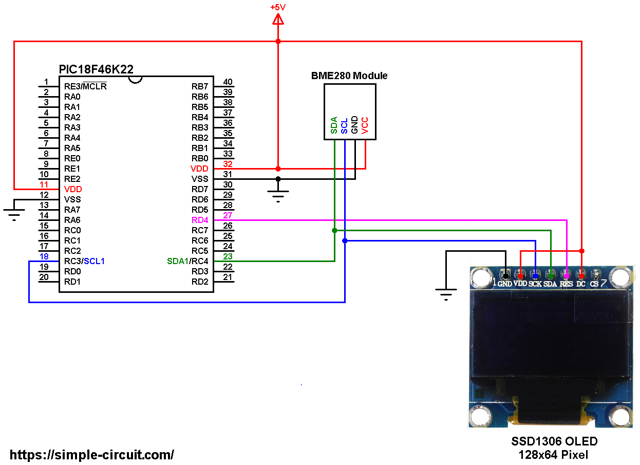
PIC18F46K22 with SSD1306 OLED and BME280 sensor circuit:
The image below shows project circuit diagram.
Hint:
The BME280 chip works with maximum voltage of 3.6V (supply voltage range is from 1.71 to 3.6V) which means we’ve to use a 3V3 voltage regulator to supply it from a 5V source.
Also, if we’re working with a 5V system (development board, microcontroller …) like the PIC18F46K22 microcontroller, we’ve to use a voltage level shifter (level converter) which converts the 3.3V (comes from the BME280 chip) into 5V (goes to the PIC18F46K22) and vice versa. This level shifter is for the I2C bus lines (clock and data).
The BME280 module shown in project circuit diagram has a built-in 3.3V regulator and level shifter.
All the grounded terminals are connected together.
The PIC18F46K22 microcontroller has 2 hardware I2C modules (MSSP1 and MSSP2 modules).
In this project I2C1 module is used with SDA1 on pin RC4 (#23) and SCL1 on pin RC3 (#18). The SDA1 pin of the MCU is connected to the SDA pin of the display and the SCL1 pin of the MCU is connected to the SCL pin of the display.
The reset pin of the display is connected to pin RD4 (#27) of the microcontroller.
The SSD1306 OLED display DC pin is connected to VDD which means I2C slave address of the device is 0x7A.
Generally, the BME280 module has at least 4 pins because it can work in SPI mode or I2C mode. For the I2C mode we need 4 pins: VCC, GND, SCL and SDA, where:
GND (ground) is connected to circuit ground (0V)
VCC is the supply pin, it is connected to +5V
SCL is I2C bus serial clock line, connected to PIC18F46K22 SCL1 (RC3) pin
SDA is I2C bus serial data line, connected to PIC18F46K22 SDA1 (RC4) pin.
The SSD1306 OLED and the BME280 sensor are connected to the same I2C bus (slave devices), SCL and SDA pins of the two devices are connected to SCL1 and SDA1 pins of the PIC18F46K22.
The I2C slave address of the SSD1306 OLED differs from the one of the BME280 sensor, this difference allows the master device (PIC18F46K22) to talk to one of them (only one at a time).
In this project the PIC18F46K22 microcontroller runs with its internal oscillator @ 16 MHz, MCLR pin is configured as an input pin.
PIC18F46K22 with SSD1306 OLED and BME280 sensor C code:
The following C code is for mikroC PRO for PIC compiler, it was tested with version 7.2.0.
To be able to compile the C code below with no error, a driver for the SSD1306 OLED display is required, its full name (with extension) is SSD1306OLED.c, download link is the one below:
SSD1306 OLED mikroC library
for more information about this driver, visit the following post:
SSD1306 OLED display library for mikroC compiler | mikroC Projects
Also, another library for the BME280 sensor is required, its full name (with extension) is BME280.c, download link is below:
BME280 Library for mikroC compiler
after the download of the 2 library files, add both of them to mikroC project folder.
The BME280 I2C address and the reset pin of the SSD1306 OLED display are defined in the C code as shown below:
1 2 3 4 5 6 | // define BME280 device I2C address: 0xEC or 0xEE (0xEE is library default address) #define BME280_I2C_ADDRESS 0xEC // SSD1306 OLED reset pin definition (if available) #define SSD1306_RST RD4_bit #define SSD1306_RST_DIR TRISD4_bit |
The driver files of the SSD1306 OLED display and the BME280 sensor are included in the code using the following 2 lines:
1 2 | #include <SSD1306OLED.c> // include SSD1306 OLED display driver source code #include <BME280.c> // include BME280 sensor driver source file |
Reading the values of temperature, humidity and pressure is done as shown below.
Note that the BME280 library returns the temperature in hundredths °C which means we’ve to divide it by 100, it returns the humidity in relative humidity percent (RH%) in 1024 steps which means we’ve to divide it by 1024 and it returns the pressure in Pa, to get the pressure in hPa we’ve to divide it by 100.
1 2 3 4 5 | // Read temperature (in hundredths C), pressure (in Pa) // and humidity (in 1024 steps RH%) values from the BME280 sensor BME280_readTemperature(&temperature); // read temperature BME280_readHumidity(&humidity); // read humidity BME280_readPressure(&pressure); // read pressure |
Temperature, humidity and pressure values are displayed on the SSD1306 OLED screen.
If there is a problem with the BME280 sensor (for example wrong device address) the screen will display Connection Error.
1 bar = 10000 Pa = 100 hPa. ( 1 hPa = 100 Pa)
Pa: Pascal
hPa: hectoPascal
Rest of code is described through comments.
Full mikroC code:
1 2 3 4 5 6 7 8 9 10 11 12 13 14 15 16 17 18 19 20 21 22 23 24 25 26 27 28 29 30 31 32 33 34 35 36 37 38 39 40 41 42 43 44 45 46 47 48 49 50 51 52 53 54 55 56 57 58 59 60 61 62 63 64 65 66 67 68 69 70 71 72 73 74 75 76 77 78 79 80 81 82 83 84 85 86 87 88 89 90 91 92 93 94 95 96 97 98 99 100 101 102 103 104 105 106 107 108 109 110 111 112 113 114 | /************************************************************************************** Interfacing PIC18F46K22 microcontroller with SSD1306 OLED (128x64 Pixel) and BME280 pressure, temperature & humidity sensor. C Code for mikroC PRO for PIC compiler. Internal oscillator used @ 16MHz Configuration words: CONFIG1H = 0x0028 CONFIG2L = 0x0018 CONFIG2H = 0x003C CONFIG3H = 0x0037 CONFIG4L = 0x0081 CONFIG5L = 0x000F CONFIG5H = 0x00C0 CONFIG6L = 0x000F CONFIG6H = 0x00E0 CONFIG7L = 0x000F CONFIG7H = 0x0040 This is a free software with NO WARRANTY. http://simple-circuit.com/ ***************************************************************************************/ // define BME280 device I2C address: 0xEC or 0xEE (0xEE is library default address) #define BME280_I2C_ADDRESS 0xEC // SSD1306 OLED reset pin definition (if available) #define SSD1306_RST RD4_bit #define SSD1306_RST_DIR TRISD4_bit #include alt;SSD1306OLED.cagt; // include SSD1306 OLED display driver source code #include alt;BME280.cagt; // include BME280 sensor driver source file const char degree[] = {0, 0, 7, 5, 7}; // degree symbol custom char // main function void main() { OSCCON = 0x70; // set internal oscillator to 16MHz ANSELC = 0; // configure all PORTC pins as digital ANSELD = 0; // configure all PORTD pins as digital I2C1_Init(400000); // initialize I2C communication with clock frequency of 400kHz delay_ms(1000); // wait a second // initialize the SSD1306 OLED with an I2C addr = 0x7A (default address) SSD1306_Begin(SSD1306_SWITCHCAPVCC, SSD1306_I2C_ADDRESS); SSD1306_ClearDisplay(); // clear the display buffer SSD1306_SetTextWrap(false); // disable text wrap SSD1306_GotoXY(0, 4); SSD1306_Print("W\r\nE\r\nA\r\nT\r\nH\r\nE\r\nR"); SSD1306_GotoXY(123, 4); SSD1306_Print("S\b\nT\b\nA\b\nT\b\nI\b\nO\b\nN"); SSD1306_Display(); // initialize the BME280 sensor according to the following settings: // BME280_begin(mode, T_sampling, H_sampling, P_sampling, filter, standby_time) if(BME280_begin(MODE_NORMAL, SAMPLING_X1, SAMPLING_X1, SAMPLING_X1, FILTER_OFF, STANDBY_0_5) == 0) { // connection error or device address wrong! SSD1306_GotoXY(34, 23); SSD1306_Print("Connection"); SSD1306_GotoXY(49, 33); SSD1306_Print("Error"); SSD1306_Display(); while(1); // stay here } SSD1306_GotoXY(29, 0); SSD1306_Print("TEMPERATURE:"); SSD1306_GotoXY(38, 23); SSD1306_Print("HUMIDITY:"); SSD1306_GotoXY(38, 46); SSD1306_Print("PRESSURE:"); SSD1306_Display(); while(1) { long temp; unsigned long humi, pres; char buffer[12]; // Read temperature (in hundredths C), pressure (in Pa) // and humidity (in 1024 steps RH%) values from the BME280 sensor BME280_readTemperature(&temp); // read temperature BME280_readHumidity(&humi); // read humidity BME280_readPressure(&pres); // read pressure // print all data on the display // 1: print temperature if(temp alt; 0) sprinti(buffer, "-%02u.%02u C\b\b", (int)(abs(temp)/100), (int)(abs(temp) % 100) ); else sprinti(buffer, " %02u.%02u C\b\b", (int)(temp/100), (int)(temp % 100) ); SSD1306_GotoXY(37, 10); SSD1306_Print(buffer); // print degree symblos ( ° ) SSD1306_PutCustomC(degree); // put degree symbol ( ° ) // 2: print humidity sprinti(buffer, "%02u.%02u %%", (int)(humi/1024), (int)(((humi*100)/1024) % 100) ); SSD1306_GotoXY(43, 33); SSD1306_Print(buffer); // 3: print pressure sprinti(buffer, "%04u.%02u hPa", (int)(pres/100), (int)(pres % 100) ); SSD1306_GotoXY(31, 56); SSD1306_Print(buffer); // now update the display SSD1306_Display(); delay_ms(1000); // wait a second } } // end of code. |
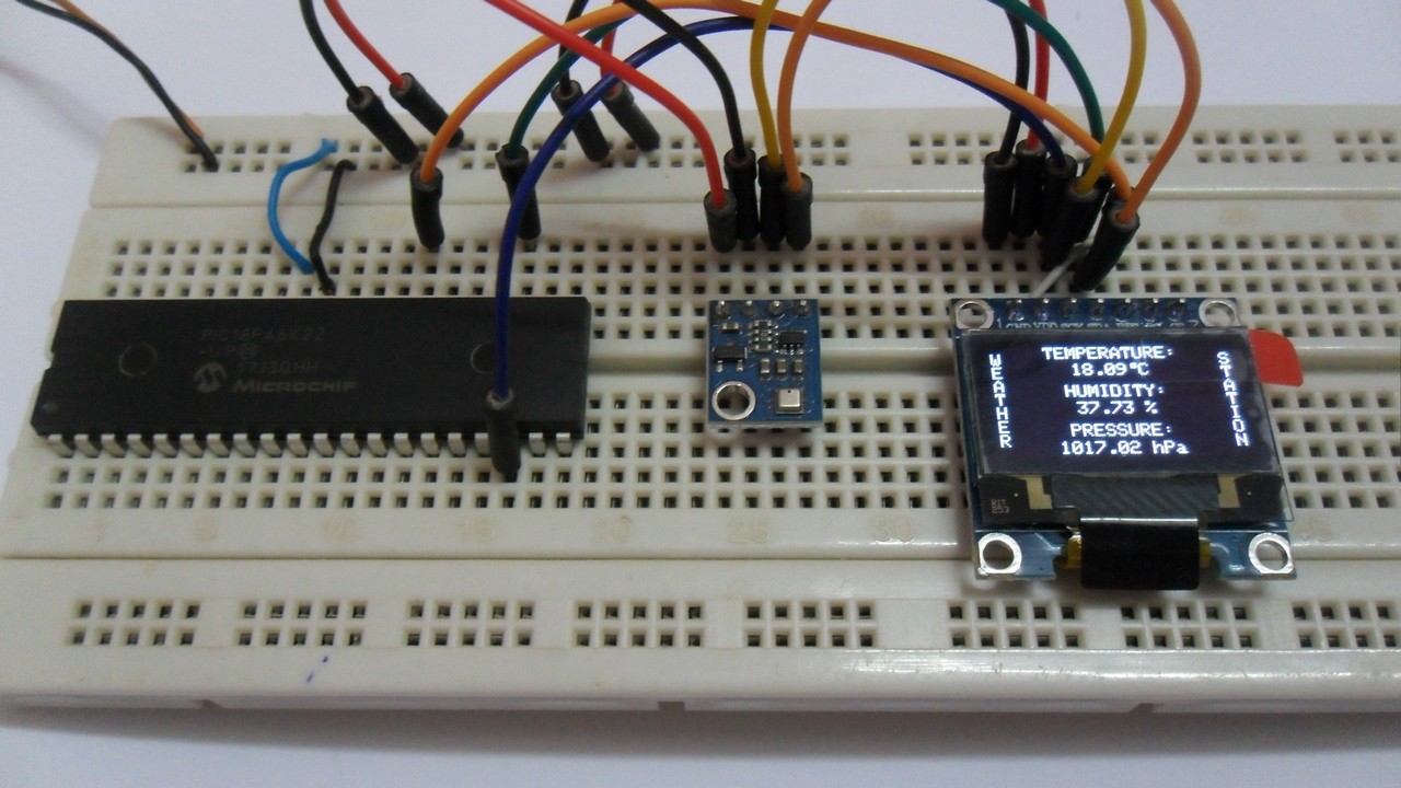
The following picture shows a protoboard circuit of the project: