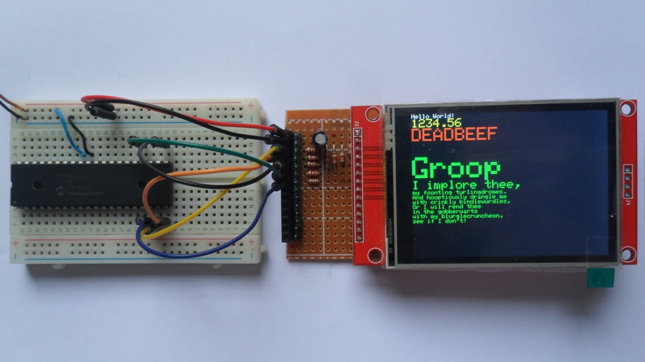
This post shows how to interface Microchip PIC18F46K22 8-bit microcontroller with ILI9341 TFT display.
The ILI9341 TFT module contains a display controller with the same name: ILI9341. It’s a color display that uses SPI interface protocol and requires 4 or 5 control pins, it’s low cost and easy to use. The resolution of this TFT display is 240 x 320 which means it has total of 76800 pixels. This module works with 3.3V only and it doesn’t support 5V (not 5V tolerant).
CCS C Compiler is used in this project.
TFT: Thin-Film Transistor.
SPI: Serial Peripheral Interface.
Project Hardware Required:
- PIC18F46K22 microcontroller —-> datasheet
- ILI9341 TFT display module (2.2″, 2.4″, 2.8″ …)
- 5 x 3.3k ohm resistor
- 5 x 2.2k ohm resistor
- 5V source
- Breadboard
- Jumper wires
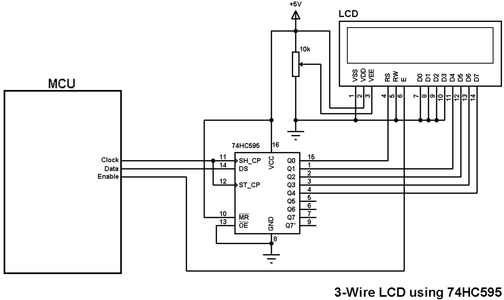
Interfacing PIC18F46K22 MCU with ILI9341 TFT display circuit:
Hardware circuit diagram of the example is shown below.
The ILI9341 TFT display board which is shown in project circuit diagram has 14 pins, the first 9 pins are for the display and the other 5 pins are for the touch module.
So, the display side pins are numbered from 1 to 9 (from left to right): VCC (5V), GND (ground), CS (chip select), RST (reset), DC (or D/C: data/command), MOSI (or SDI), SCK (clock), BL (back light LED) and MISO (or SDO).
MOSI: master-out slave-in.
SDI: serial data in.
MISO: master-in slave-out.
SDO: serial data out.

All the grounded terminals are connected together.
As mentioned above, the ILI9341 TFT display controller works with 3.3V only (power supply and control lines). The display module is supplied with 5V where GND pin is connected to circuit ground, VCC and BL pins are connected to circuit +5V. This module has a built-in 3.3V regulator which supplies the display controller with 3.3V from the 5V source.
The PIC18F46K22 microcontroller has 2 hardware SPI modules (MSSP1 and MSSP2 modules).
In this project SPI1 module is used with SCK1 on pin RC3 (#18) and SDO1 (MOSI) on pin RC5 (#24).
All PIC18F46K22 MCU output pins are 5V, connecting a 5V pin directly to the ILI9341 display board may damage its controller circuit. To avoid that, I used voltage divider for each line which means there are 5 voltage dividers. Each voltage divider consists of 2.2k and 3.3k resistors, this drops the 5V into 3V which is sufficient.
So, the ILI9341 TFT display is connected to the PIC18F46K22 MCU as follows (each one through voltage divider):
CS pin is connected to pin RD0 (#19),
RST pin is connected to pin RD1 (#20),
D/C pin is connected to pin RD2 (#21),
MOSI pin is connected to pin RC5 (#24),
SCK pin is connected to pin RC3 (#18).
In this project the PIC18F46K22 microcontroller runs with its internal oscillator @ 64 MHz, MCLR pin is configured as an input pin.
Interfacing PIC18F46K22 MCU with ILI9341 TFT display C code:
The following C code is for CCS C compiler, it was tested with versions 5.051 and 5.083.
To be able to compile project C code with no error, 2 libraries are required:
The first library is a driver for the ILI9341 TFT display, its full name (with extension) is ILI9341.c, download link is below:
ILI9341 TFT display library for CCS C compiler
The second library is graphics library, its full name is GFX_Library.c, download link is the one below:
Graphics library for CCS C compiler
after the download of the 2 library files, add both of them to the project folder.
Hints:
The 2 library files are included in the main code as shown below:
1 2 | #include <ILI9341.c> // include ILI9341 TFT display driver #include <GFX_Library.c> // include graphics library |
As mentioned above, the ILI9341 TFT is connected to PIC18F46K22 microcontroller SPI1 module pins (SCK1 and SDO1) which is initialized with the following line:
1 | #use SPI(SPI1, MODE = 0, BITS = 8, STREAM = ILI9341) |
The other pins: RST, CS and DC are defined as shown below:
1 2 3 4 | // define ILI9341 TFT module pin connections #define TFT_CS PIN_D0 // chip select pin #define TFT_RST PIN_D1 // reset pin, optional! #define TFT_DC PIN_D2 // data/command pin |
Rest of code is described through comments.
Full CCS C code:
1 2 3 4 5 6 7 8 9 10 11 12 13 14 15 16 17 18 19 20 21 22 23 24 25 26 27 28 29 30 31 32 33 34 35 36 37 38 39 40 41 42 43 44 45 46 47 48 49 50 51 52 53 54 55 56 57 58 59 60 61 62 63 64 65 66 67 68 69 70 71 72 73 74 75 76 77 78 79 80 81 82 83 84 85 86 87 88 89 90 91 92 93 94 95 96 97 98 99 100 101 102 103 104 105 106 107 108 109 110 111 112 113 114 115 116 117 118 119 120 121 122 123 124 125 126 127 128 129 130 131 132 133 134 135 136 137 138 139 140 141 142 143 144 145 146 147 148 149 150 151 152 153 154 155 156 157 158 159 160 161 162 163 164 165 166 167 168 169 170 171 172 173 174 175 176 177 178 179 180 181 182 183 184 185 186 187 188 189 190 191 192 193 194 195 196 197 198 199 200 201 202 203 204 205 206 207 208 209 210 211 212 213 214 215 216 217 218 219 220 221 222 223 224 225 226 227 228 229 230 231 232 233 234 235 236 237 238 239 240 241 242 243 244 245 246 247 248 249 250 251 252 253 254 255 256 257 258 259 260 261 262 263 264 265 266 267 268 269 270 271 272 273 274 275 276 277 278 279 280 281 282 283 284 285 286 287 288 289 290 291 292 293 294 295 | /************************************************************************** Interfacing PIC18F46K22 microcontroller with ILI9341 TFT display (240x320 pixel). C Code for CCS C compiler. This is a free software with NO WARRANTY. http://simple-circuit.com/ /*************************************************** This is our GFX example for the Adafruit ILI9341 Breakout and Shield ----> http://www.adafruit.com/products/1651 Check out the links above for our tutorials and wiring diagrams These displays use SPI to communicate, 4 or 5 pins are required to interface (RST is optional) Adafruit invests time and resources providing this open source code, please support Adafruit and open-source hardware by purchasing products from Adafruit! Written by Limor Fried/Ladyada for Adafruit Industries. MIT license, all text above must be included in any redistribution ****************************************************/ // define ILI9341 TFT module pin connections #define TFT_CS PIN_D0 // chip select pin #define TFT_RST PIN_D1 // reset pin, optional! #define TFT_DC PIN_D2 // data/command pin #include <18F46K22.h> #fuses NOMCLR,NOLVP,NOBROWNOUT,PUT,NOXINST #use delay(internal = 64MHz) #use SPI(SPI1, MODE = 0, BITS = 8, STREAM = ILI9341) #include <ILI9341.c> // include ILI9341 TFT display driver #include <GFX_Library.c> // include graphics library void testFillScreen() { display_fillScreen(ILI9341_BLACK); display_fillScreen(ILI9341_RED); display_fillScreen(ILI9341_GREEN); display_fillScreen(ILI9341_BLUE); display_fillScreen(ILI9341_BLACK); } void testText() { display_fillScreen(ILI9341_BLACK); display_setCursor(0, 0); display_setTextColor(ILI9341_WHITE); display_setTextSize(1); display_print("Hello World!\r\n"); display_setTextColor(ILI9341_YELLOW); display_setTextSize(2); printf(display_print, "%f\r\n", 1234.56); display_setTextColor(ILI9341_RED); display_setTextSize(3); printf(display_print, "%LX\r\n", 0xDEADBEEF); display_print("\r\n"); // start a new line display_setTextColor(ILI9341_GREEN); display_setTextSize(5); display_print("Groop\r\n"); display_setTextSize(2); display_print("I implore thee,\r\n"); display_setTextSize(1); display_print("my foonting turlingdromes.\r\n"); display_print("And hooptiously drangle me\r\n"); display_print("with crinkly bindlewurdles,\r\n"); display_print("Or I will rend thee\r\n"); display_print("in the gobberwarts\r\n"); display_print("with my blurglecruncheon,\r\n"); display_print("see if I don't!\r\n"); } void testLines(uint16_t color) { int16_t x1, y1, x2, y2, w = display_width, h = display_height; display_fillScreen(ILI9341_BLACK); x1 = y1 = 0; y2 = h - 1; for(x2=0; x2<w; x2+=6) display_drawLine(x1, y1, x2, y2, color); x2 = w - 1; for(y2=0; y2<h; y2+=6) display_drawLine(x1, y1, x2, y2, color); display_fillScreen(ILI9341_BLACK); x1 = w - 1; y1 = 0; y2 = h - 1; for(x2=0; x2<w; x2+=6) display_drawLine(x1, y1, x2, y2, color); x2 = 0; for(y2=0; y2<h; y2+=6) display_drawLine(x1, y1, x2, y2, color); display_fillScreen(ILI9341_BLACK); x1 = 0; y1 = h - 1; y2 = 0; for(x2=0; x2<w; x2+=6) display_drawLine(x1, y1, x2, y2, color); x2 = w - 1; for(y2=0; y2<h; y2+=6) display_drawLine(x1, y1, x2, y2, color); display_fillScreen(ILI9341_BLACK); x1 = w - 1; y1 = h - 1; y2 = 0; for(x2=0; x2<w; x2+=6) display_drawLine(x1, y1, x2, y2, color); x2 = 0; for(y2=0; y2<h; y2+=6) display_drawLine(x1, y1, x2, y2, color); } void testFastLines(uint16_t color1, uint16_t color2) { int16_t x, y, w = display_width, h = display_height; display_fillScreen(ILI9341_BLACK); for(y=0; y<h; y+=5) display_drawHLine(0, y, w, color1); for(x=0; x<w; x+=5) display_drawVLine(x, 0, h, color2); } void testRects(uint16_t color) { int16_t n, i, i2, cx = display_width / 2, cy = display_height / 2; display_fillScreen(ILI9341_BLACK); n = min(display_width, display_height); for(i=2; i<n; i+=6) { i2 = i / 2; display_drawRect(cx-i2, cy-i2, i, i, color); } } void testFilledRects(uint16_t color1, uint16_t color2) { int16_t n, i, i2, cx = display_width / 2 - 1, cy = display_height / 2 - 1; display_fillScreen(ILI9341_BLACK); n = min(display_width, display_height); for(i=n; i>0; i-=6) { i2 = i / 2 - 1; display_fillRect(cx-i2, cy-i2, i, i, color1); // Outlines are not included in timing results display_drawRect(cx-i2, cy-i2, i, i, color2); } } void testFilledCircles(uint8_t radius, uint16_t color) { int16_t x, y, w = display_width, h = display_height, r2 = radius * 2; display_fillScreen(ILI9341_BLACK); for(x=radius; x<w; x+=r2) { for(y=radius; y<h; y+=r2) { display_fillCircle(x, y, radius, color); } } } void testCircles(uint8_t radius, uint16_t color) { int16_t x, y, r2 = radius * 2, w = display_width + radius, h = display_height + radius; for(x=0; x<w; x+=r2) { for(y=0; y<h; y+=r2) { display_drawCircle(x, y, radius, color); } } } void testTriangles() { int16_t n, i, cx = display_width / 2 - 1, cy = display_height / 2 - 1; uint16_t color = 0xF600; display_fillScreen(ILI9341_BLACK); n = min(cx, cy); for(i=0; i<n; i+=5) { display_drawTriangle( cx , cy - i, // peak cx - i, cy + i, // bottom left cx + i, cy + i, // bottom right color); color += 100; } } void testFilledTriangles() { int16_t i, cx = display_width / 2 - 1, cy = display_height / 2 - 1; display_fillScreen(ILI9341_BLACK); for(i=min(cx,cy); i>10; i-=5) { display_fillTriangle(cx, cy - i, cx - i, cy + i, cx + i, cy + i, display_color565(0, i*2, i*2)); display_drawTriangle(cx, cy - i, cx - i, cy + i, cx + i, cy + i, display_color565(i*2, i*2, 0)); } } void testRoundRects() { int16_t w, i, i2, cx = display_width / 2 - 1, cy = display_height / 2 - 1; display_fillScreen(ILI9341_BLACK); w = min(display_width, display_height); for(i=0; i<w; i+=6) { i2 = i / 2; display_drawRoundRect(cx-i2, cy-i2, i, i, i/8, display_color565(i, 0, 0)); } } void testFilledRoundRects() { int16_t i, i2, cx = display_width / 2 - 1, cy = display_height / 2 - 1; display_fillScreen(ILI9341_BLACK); for(i=min(display_width, display_height); i>20; i-=6) { i2 = i / 2; display_fillRoundRect(cx-i2, cy-i2, i, i, i/8, display_color565(0, i, 0)); } } // main function void main(void) { // initialize ILI9341 TFT tft_begin(); // init done! delay_ms(10); testFillScreen(); delay_ms(500); testText(); delay_ms(3000); testLines(ILI9341_CYAN); delay_ms(500); testFastLines(ILI9341_RED, ILI9341_BLUE); delay_ms(500); testRects(ILI9341_GREEN); delay_ms(500); testFilledRects(ILI9341_YELLOW, ILI9341_MAGENTA); delay_ms(500); testFilledCircles(10, ILI9341_MAGENTA); testCircles(10, ILI9341_WHITE); delay_ms(500); testTriangles(); delay_ms(500); testFilledTriangles(); delay_ms(500); testRoundRects(); delay_ms(500); testFilledRoundRects(); delay_ms(500); while(TRUE) { for(uint8_t rotation=0; rotation<4; rotation++) { display_setRotation(rotation); testText(); delay_ms(1000); } } } // end of code. |
The video below shows my breadboard test circuit:
Proteus simulation:
We can simulate this project with Proteus ISIS software as shown in the following video (not perfect result as the hardware circuit).
Note that Proteus simulation circuit is not the same as real hardware circuit, project hardware circuit diagram is shown above.
Proteus simulation file download link is below, use version 8.6 or higher to open it:
PIC18F46K22 and ILI9341 TFT Proteus simulation
Hi
I am trying to port your program to HI-Tech c but have an error ) missing in the last line.
void startWrite(void);
void endWrite(void);
void writeCommand(uint8_t cmd);
void setAddrWindow(uint16_t x1, uint16_t y1, uint16_t w, uint16_t h)
uint8_t tft_readcommand8(uint8_t reg, uint8_t index=0);
Could please help me solve the problem?
hi. need info.
my CCS C compiler does not include the PIC18F46K22 in the device.dat,
and my PicKit 2 have same problem
What shall I do ?
What hardware og software do you uses ?
I dont have an URL.
Hello Author can i contact you via mail???. Please reply as soon as possible.