This is another example that shows how to interface PIC18F46K22 microcontroller with ST7735 SPI TFT display. In this project I’m going to do a simple rotation test to the ST7735 TFT display.
The last project is a graphics test of the ST7735 TFT display, project link is below:
Interfacing PIC18F46K22 MCU with ST7735 TFT – Graphics Test Example
CCS C Compiler is used in this project.
Project Hardware Required:
- PIC18F46K22 microcontroller —-> datasheet
- ST7735 TFT display module (ST7735R or ST7735S)
- Push button
- 5 x 1k ohm resistor
- 5V source
- Breadboard
- Jumper wires
Interfacing PIC18F46K22 MCU with ST7735 TFT circuit:
Project circuit schematic diagram is shown below.
The ST7735S shown in project circuit diagram has 8 pins: (from right to left): RST (reset), CS (chip select), DC (or D/C: data/command), DIN (data in), CLK (clock), VCC, BL (back light) and Gnd (ground).
The ST7735 display module is supplied with 5V. GND pin is connected to circuit ground, VCC and BL pins are connected to circuit +5V.
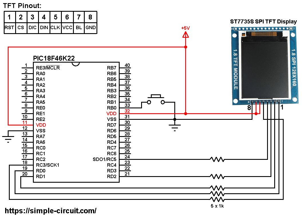
All the grounded terminals are connected together.
The PIC18F46K22 microcontroller has 2 hardware SPI modules (MSSP1 and MSSP2 modules).
In this project SPI1 module is used with SCK1 on pin RC3 (#18) and SDO1 (MOSI) on pin RC5 (#24). SCK1 and SDO1 pins of the PIC18F46K22 MCU are respectively connected to CLK and DIN pins of the ST7735S display module.
SCK: Serial Clock.
SDO: Serial Data-Out, synonym for MOSI.
MOSI: Master-Out Slave-In.
All PIC18F46K22 MCU output pins are 5V, connecting a 5V pin directly to the ST7735 display board may damage its controller circuit. To avoid that, I connected each control line of the display to the microcontroller through 1k ohm resistor.
So, the ST7735 display is connected to the PIC18F46K22 MCU as follows (each one through 1k resistor):
RST pin is connected to pin RD0 (#19),
CS pin is connected to pin RD1 (#20),
D/C pin is connected to pin RD2 (#21),
DIN pin is connected to pin RC5 (#24),
CLK pin is connected to pin RC3 (#18).
In this project the PIC18F46K22 microcontroller runs with its internal oscillator @ 32 MHz, MCLR pin is configured as an input pin.
Interfacing PIC18F46K22 MCU with ST7735 TFT C code:
The following C code is for CCS C compiler, it was tested with versions 5.051 and 5.083.
To be able to compile project C code with no error, 2 libraries are required:
The first library is a driver for the ST7735 TFT display, its full name (with extension) is ST7735.c, download link is below:
ST7735 TFT display library for CCS C compiler
The second library is graphics library, its full name is GFX_Library.c, download link is the one below:
Graphics library for CCS C compiler
after the download of the 2 library files, add both of them to the project folder.
Hints:
The 2 library files are included in the main code as shown below:
1 2 | #include <ST7735.c> // include ST7735 driver source code #include <GFX_Library.c> // include graphics library source code |
As mentioned above, the ST7735 TFT is connected to PIC18F46K22 microcontroller SPI1 module pins (SCK1 and SDO1) which is initialized with the following line:
1 | #use SPI(SPI1, MODE = 0, BITS = 8, STREAM = ST7735) |
The other pins: RST, CS and DC are defined as shown below:
1 2 3 4 | // define ST7735 TFT module pin connections #define TFT_RST PIN_D0 // reset pin, optional! #define TFT_CS PIN_D1 // chip select pin #define TFT_DC PIN_D2 // data/command pin |
The push button is connected to pin RB0 (#33), it’s defined in the C code as:
1 2 | // define button connection #define button PIN_B0 |
Full CCS C code:
1 2 3 4 5 6 7 8 9 10 11 12 13 14 15 16 17 18 19 20 21 22 23 24 25 26 27 28 29 30 31 32 33 34 35 36 37 38 39 40 41 42 43 44 45 46 47 48 49 50 51 52 53 54 55 56 57 58 59 60 61 62 63 64 65 66 67 68 69 70 71 72 73 74 75 76 77 78 79 80 81 82 83 84 85 86 87 88 89 90 91 92 93 94 95 96 97 98 99 100 101 102 103 104 105 106 107 108 109 110 111 112 113 114 115 116 117 118 119 120 121 122 123 124 125 126 127 128 129 130 131 132 133 134 135 136 137 138 139 140 141 142 143 144 145 146 147 148 149 150 151 152 153 154 155 156 157 158 159 160 161 162 163 164 165 166 167 168 169 170 171 172 173 174 175 176 177 178 179 180 181 182 183 184 185 186 187 188 189 190 191 192 193 194 195 196 197 198 199 200 201 202 203 204 205 206 207 208 209 210 211 212 213 214 215 216 217 218 219 220 221 222 223 224 225 226 227 228 229 230 231 232 233 234 235 236 237 238 239 240 241 242 243 244 245 246 247 248 249 250 251 252 253 254 255 256 257 258 259 260 261 262 263 264 265 266 | /************************************************************************** Interfacing PIC18F46K22 microcontroller with ST7735S TFT display. Rotation test example. C Code for CCS C compiler. This is a free software with NO WARRANTY. http://simple-circuit.com/ /*************************************************** This is a library for the Adafruit 1.8" SPI display. This library works with the Adafruit 1.8" TFT Breakout w/SD card ----> http://www.adafruit.com/products/358 The 1.8" TFT shield ----> https://www.adafruit.com/product/802 The 1.44" TFT breakout ----> https://www.adafruit.com/product/2088 as well as Adafruit raw 1.8" TFT display ----> http://www.adafruit.com/products/618 Check out the links above for our tutorials and wiring diagrams These displays use SPI to communicate, 4 or 5 pins are required to interface (RST is optional) Adafruit invests time and resources providing this open source code, please support Adafruit and open-source hardware by purchasing products from Adafruit! Written by Limor Fried/Ladyada for Adafruit Industries. MIT license, all text above must be included in any redistribution ****************************************************/ // define ST7735 TFT module pin connections #define TFT_RST PIN_D0 // reset pin, optional! #define TFT_CS PIN_D1 // chip select pin #define TFT_DC PIN_D2 // data/command pin #include <18F46K22.h> #fuses NOMCLR,NOLVP,NOBROWNOUT,PUT,NOXINST #use delay(internal = 32MHz) #use SPI(SPI1, MODE = 0, BITS = 8, STREAM = ST7735) #include <ST7735.c> // include ST7735 driver source code #include <GFX_Library.c> // include graphics library source code // define button connection #define button PIN_B0 void rotateText() { for (uint8_t i=0; i<4; i++) { display_fillScreen(ST7735_BLACK); display_setCursor(0, 30); display_setTextColor(ST7735_RED); display_setTextSize(1); display_print("Hello World!\r\n"); display_setTextColor(ST7735_YELLOW); display_setTextSize(2); display_print("Hello World!\r\n"); display_setTextColor(ST7735_GREEN); display_setTextSize(3); display_print("Hello World!\r\n"); display_setTextColor(ST7735_BLUE); display_setTextSize(4); printf(display_print, "%f", 1234.567); while( input(button) ); // wait for button press display_setRotation(display_getRotation()+1); } } void rotateFillcircle(void) { for (uint8_t i=0; i<4; i++) { display_fillScreen(ST7735_BLACK); display_fillCircle(10, 30, 10, ST7735_YELLOW); while( input(button) ); // wait for button press display_setRotation(display_getRotation()+1); } } void rotateDrawcircle(void) { for (uint8_t i=0; i<4; i++) { display_fillScreen(ST7735_BLACK); display_drawCircle(10, 30, 10, ST7735_YELLOW); while( input(button) ); // wait for button press display_setRotation(display_getRotation()+1); } } void rotateFillrect(void) { for (uint8_t i=0; i<4; i++) { display_fillScreen(ST7735_BLACK); display_fillRect(10, 20, 10, 20, ST7735_GREEN); while( input(button) ); // wait for button press display_setRotation(display_getRotation()+1); } } void rotateDrawrect(void) { for (uint8_t i=0; i<4; i++) { display_fillScreen(ST7735_BLACK); display_drawRect(10, 20, 10, 20, ST7735_GREEN); while( input(button) ); // wait for button press display_setRotation(display_getRotation()+1); } } void rotateFastline(void) { for (uint8_t i=0; i<4; i++) { display_fillScreen(ST7735_BLACK); display_drawHLine(0, 20, display_width, ST7735_RED); display_drawVLine(20, 0, display_height, ST7735_BLUE); while( input(button) ); // wait for button press display_setRotation(display_getRotation()+1); } } void rotateLine(void) { for (uint8_t i=0; i<4; i++) { display_fillScreen(ST7735_BLACK); display_drawLine(display_width/2, display_height/2, 0, 0, ST7735_RED); while( input(button) ); // wait for button press display_setRotation(display_getRotation()+1); } } void rotatePixel(void) { for (uint8_t i=0; i<4; i++) { display_fillScreen(ST7735_BLACK); display_drawPixel(10,20, ST7735_WHITE); while( input(button) ); // wait for button press display_setRotation(display_getRotation()+1); } } void rotateTriangle(void) { for (uint8_t i=0; i<4; i++) { display_fillScreen(ST7735_BLACK); display_drawTriangle(20, 10, 10, 30, 30, 30, ST7735_GREEN); while( input(button) ); // wait for button press display_setRotation(display_getRotation()+1); } } void rotateFillTriangle(void) { for (uint8_t i=0; i<4; i++) { display_fillScreen(ST7735_BLACK); display_fillTriangle(20, 10, 10, 30, 30, 30, ST7735_RED); while( input(button) ); // wait for button press display_setRotation(display_getRotation()+1); } } void rotateRoundRect(void) { for (uint8_t i=0; i<4; i++) { display_fillScreen(ST7735_BLACK); display_drawRoundRect(20, 10, 25, 15, 5, ST7735_BLUE); while( input(button) ); // wait for button press display_setRotation(display_getRotation()+1); } } void rotateFillRoundRect(void) { for (uint8_t i=0; i<4; i++) { display_fillScreen(ST7735_BLACK); display_fillRoundRect(20, 10, 25, 15, 5, ST7735_CYAN); while( input(button) ); // wait for button press display_setRotation(display_getRotation()+1); } } void rotateChar(void) { for (uint8_t i=0; i<4; i++) { display_fillScreen(ST7735_BLACK); display_drawChar(25, 15, 'A', ST7735_WHITE, ST7735_WHITE, 1); while( input(button) ); // wait for button press display_setRotation(display_getRotation()+1); } } void rotateString(void) { for (uint8_t i=0; i<4; i++) { display_fillScreen(ST7735_BLACK); display_setCursor(8, 25); display_setTextSize(1); display_setTextColor(ST7735_WHITE); display_print("Adafruit Industries"); while( input(button) ); // wait for button press display_setRotation(display_getRotation()+1); } } // main function void main(void) { port_b_pullups(0x01); // enable RB0 internal pull-ups // Use this initializer if using a 1.8" TFT screen: tft_initR(INITR_BLACKTAB); // Init ST7735S chip, black tab // OR use this initializer (uncomment) if using a 1.44" TFT: //tft_initR(INITR_144GREENTAB); // Init ST7735R chip, green tab // OR use this initializer (uncomment) if using a 0.96" 180x60 TFT: //tft_initR(INITR_MINI160x80); // Init ST7735S mini display display_setTextWrap(false); // Allow text to run off right edge display_fillScreen(ST7735_BLACK); while(TRUE) { rotateLine(); rotateText(); rotatePixel(); rotateFastline(); rotateDrawrect(); rotateFillrect(); rotateDrawcircle(); rotateFillcircle(); rotateTriangle(); rotateFillTriangle(); rotateRoundRect(); rotateFillRoundRect(); rotateChar(); rotateString(); } } // end of code. |
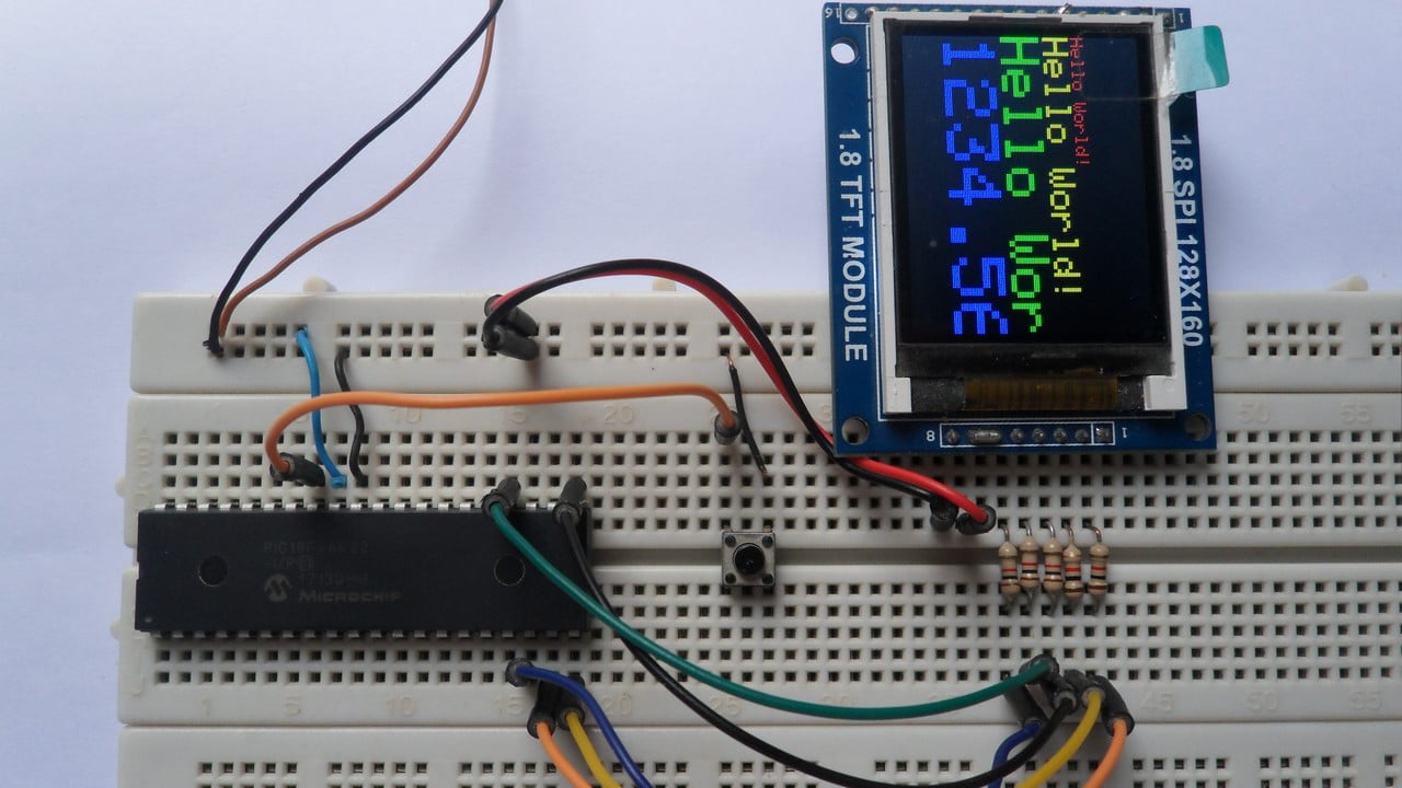
My test hardware circuit is shown in the video below:
Proteus simulation:
We can simulate this project with Proteus ISIS software as shown in the following video:
Proteus simulation file download link is below, use version 8.6 or higher to open it:
PIC18F46K22 + ST7735 TFT Proteus simulation