Topics related to this post:
LED Blink with PIC16F887 microcontroller
PIC16F887 Timers and Interrupts
This post shows the making of a simple 4-channel RF (Radio Frequency) remote control system based on PIC16F887 microcontroller.
The RF remote control system consists of two parts, transmitter part and receiver part. Both parts are based on the same microcontroller type which is PIC16F887. The transmitter circuit contains an RF transmitter which is responsible for transmitting RF signals while the receiver circuit contains an RF receiver which receives the RF signals transmitted by the transmitter circuit. Module frequency can be 315MHz or 433MHz. I used the module shown in the picture below:
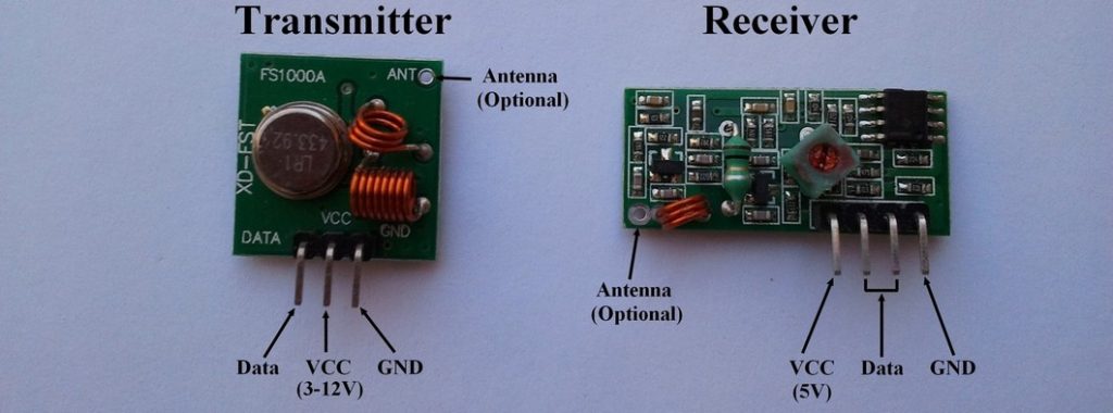
The RF transmitter can be powered from 3 to 12V depending on the range required (more voltage —> more transmission range).
Communication protocol:
In this RF project NEC protocol is used to send data from the transmitter circuit to the receiver circuit. More details about the NEC protocol and how to decode it using PIC16F887 in the following topic:
NEC Protocol decoder with PIC16F887 microcontroller
The difference between the IR and RF receivers is that the IR receiver output is logic 0 (0V) while it receives an IR pulse and its idle state is logic 1 (5V). For the RF receiver the situation is reversed, the idle state is logic 0 and the active sate is logic 1.
Hardware Required:
1 – RF Transmitter circuit:
- PIC16F887 microcontroller
- 433MHz / 315MHz RF transmitter
- 4 x push button
- 5V voltage source
- Breadboard
- Jumper wires
2 – RF Receiver circuit:
- PIC16F887 microcontroller
- 433MHz / 315MHz RF receiver
- 100µF capacitor
- 4 x LED
- 4 x 470 ohm resistor
- 5V voltage source
- Breadboard
- Jumper wires
RF Transmitter and receiver system using PIC16F887 circuit:
1 – RF Transmitter circuit:
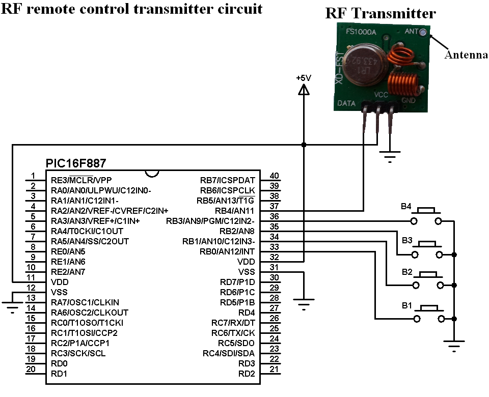
In the RF transmitter circuit there are 4 push buttons connected to RB0, RB1, RB2 and RB3, each button sends a different RF code via the RF transmitter where the RF transmitter data pin is connected to RB4.
The internal pull-ups of PORTB input pins are enabled in the software.
In this project PIC16F887 uses its internal oscillator and MCLR pin function is disabled.
2 – RF Receiver circuit:
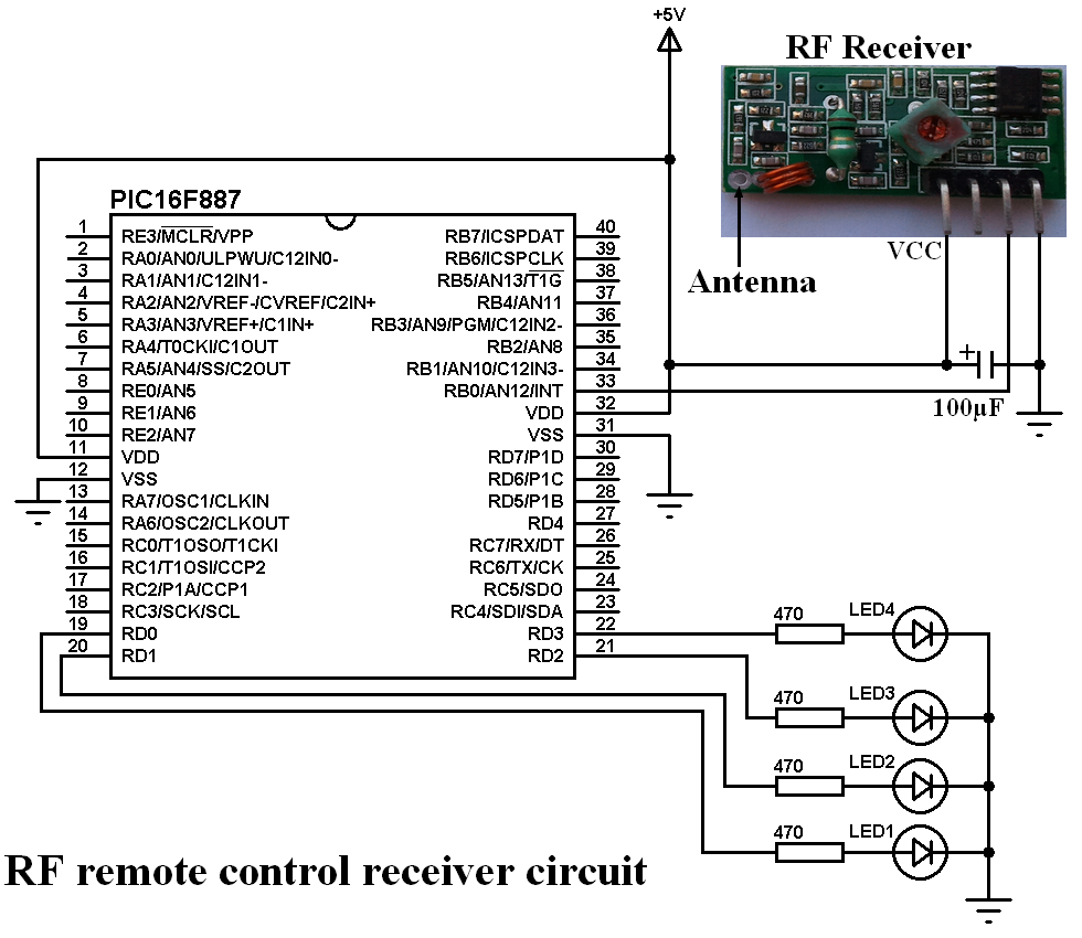
In the receiver circuit there are 4 LEDs, these LEDs are connected to pins RD0, RD1, RD2 and RD3 through 470 ohm resistors. Each LED is controlled from a push button in the RF transmitter circuit.
The RF receiver data pin is connected to pin RB0 which is the external interrupt pin of the PIC16F887. A 100µF capacitor should be added between VCC and GND of the RF receiver.
In this circuit also the PIC16F887 uses its internal oscillator and MCLR pin function is disabled.
RF Transmitter and receiver system using PIC16F887 C code:
The following C code are for CCS PIC C compiler.
1 – RF Transmitter code:
The first code is for the RF transmitter circuit microcontroller. The transmitter circuit has 4 push buttons: B1, B2, B3 and B4. Each button sends a code through the RF transmitter as follows (32-bit codes):
B1 ——–> 0x00FF00FF
B2 ——–> 0x00FF807F
B3 ——–> 0x00FF40BF
B4 ——–> 0x00FF20DF
The full C code is below.
1 2 3 4 5 6 7 8 9 10 11 12 13 14 15 16 17 18 19 20 21 22 23 24 25 26 27 28 29 30 31 32 33 34 35 36 37 38 39 40 41 42 43 44 45 46 47 48 49 50 51 52 53 54 55 56 57 58 59 60 61 62 63 64 65 | /* RF transmitter using PIC16F887 microcontroller CCS C code This RF transmitter is based on NEC protocol Internal oscillator used @ 8MHz */ #include <16F887.h> #fuses NOMCLR, NOBROWNOUT, NOLVP, INTRC_IO #use delay(clock = 8MHz) #use fast_io(B) void send_signal(unsigned int32 number){ int8 i; // Send 9ms pulse output_high(PIN_B4); delay_ms(9); // Send 4.5ms space output_low(PIN_B4); delay_us(4500); // Send data (32 bits) for(i = 0; i < 32; i++){ // If bit is 1 send 560us pulse and 1680us space if(bit_test(number, 31 - i)){ output_high(PIN_B4); delay_us(560); output_low(PIN_B4); delay_us(1680); } // If bit is 0 send 560us pulse and 560us space else{ output_high(PIN_B4); delay_us(560); output_low(PIN_B4); delay_us(560); } } // Send end bit output_high(PIN_B4); delay_us(560); output_low(PIN_B4); delay_us(560); } void main() { setup_oscillator(OSC_8MHZ); // Set internal oscillator to 8MHz output_b(0); set_tris_b(0x0F); // Configure RB0, RB1, RB2 and RB3 as inputs port_b_pullups(0x0F); // Enable internal pull-ups for pins RB0,RB1,RB2 and RB3 while(TRUE){ if(!input(PIN_B0)){ // If RB0 button is pressed send_signal(0x00FF00FF); delay_ms(500); } if(!input(PIN_B1)){ // If RB1 button is pressed send_signal(0x00FF807F); delay_ms(500); } if(!input(PIN_B2)){ // If RB2 button is pressed send_signal(0x00FF40BF); delay_ms(500); } if(!input(PIN_B3)){ // If RB3 button is pressed send_signal(0x00FF20DF); delay_ms(500); } } } |
2 – RF Receiver code:
The output of the RF receiver is connected to the external interrupt pin (RB0) and this interrupt is used to detect any incoming signal (even noise).
Timer1 module is used to measure pulse and space widths and also Timer1 interrupt is used to reset the decoding process in case of very long pulse or space ( > 65.535 ms). Timer1 is configured to increment every 1µs using the following line:
setup_timer_1( T1_INTERNAL | T1_DIV_BY_2 );
The microcontroller will not do any thing until the complete decoding process is completed and at the end of the decoding process the variable code_ok is set ( = 1).
The variable nec_state is used to define the decoding process state, totally there are 5 states:
State 0: beginning of decoding process which is the beginning of 9ms pulse.
State 1: start of 4.5ms space
State 2: start of 560µs pulse
State 3: start of 560µs pulse or 1680 space
State 4: end of 560µs pulse or 1680 space
The full C code of the RF receiver is below.
1 2 3 4 5 6 7 8 9 10 11 12 13 14 15 16 17 18 19 20 21 22 23 24 25 26 27 28 29 30 31 32 33 34 35 36 37 38 39 40 41 42 43 44 45 46 47 48 49 50 51 52 53 54 55 56 57 58 59 60 61 62 63 64 65 66 67 68 69 70 71 72 73 74 75 76 77 78 79 80 81 82 83 84 85 86 87 88 89 90 91 92 93 94 95 96 97 98 99 100 101 102 103 104 105 106 | /* RF Receiver using PIC16F887 microcontroller CCS C code This RF receiver is based on NEC protocol Internal oscillator used @ 8MHz */ #include <16F887.h> #fuses NOMCLR, NOBROWNOUT, NOLVP, INTRC_IO #use delay(clock = 8MHz) #use fast_io(D) short code_ok = 0; unsigned int8 nec_state = 0, i; unsigned int32 rf_code; #INT_EXT // External interrupt void ext_isr(void){ unsigned int16 time; if(nec_state != 0){ time = get_timer1(); // Store Timer1 value set_timer1(0); // Reset Timer1 } switch(nec_state){ case 0 : // Start receiving IR data (we're at the beginning of 9ms pulse) setup_timer_1( T1_INTERNAL | T1_DIV_BY_2 ); // Enable Timer1 module with internal clock source and prescaler = 2 set_timer1(0); // Reset Timer1 value nec_state = 1; // Next state: end of 9ms pulse (start of 4.5ms space) i = 0; ext_int_edge( H_TO_L ); // Toggle external interrupt edge return; case 1 : // End of 9ms pulse if((time > 9500) || (time < 8500)){ // Invalid interval ==> stop decoding and reset nec_state = 0; // Reset decoding process setup_timer_1(T1_DISABLED); // Stop Timer1 module } else nec_state = 2; // Next state: end of 4.5ms space (start of 560µs pulse) ext_int_edge( L_TO_H ); // Toggle external interrupt edge return; case 2 : // End of 4.5ms space if((time > 5000) || (time < 4000)){ // Invalid interval ==> stop decoding and reset nec_state = 0; // Reset decoding process setup_timer_1(T1_DISABLED); // Stop Timer1 module return; } nec_state = 3; // Next state: end of 560µs pulse (start of 560µs or 1680µs space) ext_int_edge( H_TO_L ); // Toggle external interrupt edge return; case 3 : // End of 560µs pulse if((time > 700) || (time < 400)){ // Invalid interval ==> stop decoding and reset nec_state = 0; // Reset decoding process setup_timer_1(T1_DISABLED); // Disable Timer1 module } else nec_state = 4; // Next state: end of 560µs or 1680µs space ext_int_edge( L_TO_H ); // Toggle external interrupt edge return; case 4 : // End of 560µs or 1680µs space if((time > 1800) || (time < 400)){ // Invalid interval ==> stop decoding and reset nec_state = 0; // Reset decoding process setup_timer_1(T1_DISABLED); // Disable Timer1 module return; } if( time > 1000) // If space width > 1ms (short space) bit_set(rf_code, (31 - i)); // Write 1 to bit (31 - i) else // If space width < 1ms (long space) bit_clear(rf_code, (31 - i)); // Write 0 to bit (31 - i) i++; if(i > 31){ // If all bits are received code_ok = 1; // Decoding process OK disable_interrupts(INT_EXT); // Disable the external interrupt } nec_state = 3; // Next state: end of 560µs pulse (start of 560µs or 1680µs space) ext_int_edge( H_TO_L ); // Toggle external interrupt edge } } #INT_TIMER1 // Timer1 interrupt (used for time out) void timer1_isr(void){ nec_state = 0; // Reset decoding process ext_int_edge( L_TO_H ); // External interrupt edge from high to low setup_timer_1(T1_DISABLED); // Disable Timer1 module clear_interrupt(INT_TIMER1); // Clear Timer1 interrupt flag bit } void main() { setup_oscillator(OSC_8MHZ); // Set internal oscillator to 8MHz output_d(0); // PORTD initial state set_tris_d(0); // Configure PORTD pins as outputs enable_interrupts(GLOBAL); // Enable global interrupts enable_interrupts(INT_EXT_L2H); // Enable external interrupt clear_interrupt(INT_TIMER1); // Clear Timer1 interrupt flag bit enable_interrupts(INT_TIMER1); // Enable Timer1 interrupt while(TRUE){ if(code_ok){ // If the mcu successfully receives NEC protocol message code_ok = 0; // Reset decoding process nec_state = 0; setup_timer_1(T1_DISABLED); // Disable Timer1 module if(rf_code == 0x00FF00FF) output_toggle(PIN_D0); if(rf_code == 0x00FF807F) output_toggle(PIN_D1); if(rf_code == 0x00FF40BF) output_toggle(PIN_D2); if(rf_code == 0x00FF20DF) output_toggle(PIN_D3); enable_interrupts(INT_EXT_L2H); // Enable external interrupt } } } |
The following video shows our example in hardware circuits:


Plz.i want hex file of 8 ch remote rf using pic16f877a
i want to change data input pin b0 to c4,how can i do,can you provide the coad for pic16f886
The portion in the transmit code (if(bit_test (number, 31-i) please help me understand. I know bit_test do test single bit in this case bit (31)
Question 1. What point did it starts testing other bits?
2.perpose of (-i) in bit_test (number, 31-i).
Hello,
Nice information,,,
Which software used for complie,,,this software,,,and any coad for proton compiler…?
Both C codes are for CCS C compiler.
Hi, just wondering where can I get all the libraries that you use?
The 2 codes do not use any external library, just they’re written with CCS C compiler.