This project shows how to use low cost 433MHz RF transmitter/receiver modules to build a 5-channel wireless RF remote control system using 2xPIC18F4550 microcontrollers.
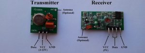
The used RF modules in this project are cheap and easy to use with any microcontroller. These modules are shown below with pin configuration:
The following video shows how to get started with low cost RF modules:
Communication protocol:
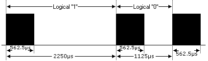
In this RF project data is transmitted from the transmitter circuit to the receiver circuit using NEC protocol. The NEC protocol uses pulse distance encoding of the bits. Each pulse is a 562.5µs long.
Logic 0: 562.5µs pulse burst followed by a 562.5µs space, with a total transmit time of 1125µs (562.5 x 2).
Logic 1: a 562.5µs pulse burst followed by a 1687.5µs (562.5 x 3) space, with a total transmit time of 2250µs (562.5 x 4).
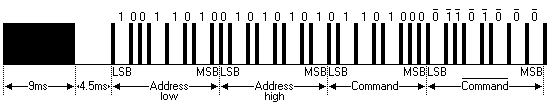
The complete extended NEC protocol message is started by 9ms burst followed by 4.5ms space which is then followed by the Address and Command. The address is 16-bit length and the command is transmitted twice (8 bits + 8 bits) where in the second time all bits are inverted and can be used for verification of the received message. The following drawing shows an extended NEC message example.
5-Channel RF remote control using PIC18F4550 microcontroller:
This 433MHz RF remote control system has 2 circuits which are transmitter circuit which transmits the RF signals and receiver circuit which receives the RF signals.
RF Transmitter circuit:
The following image shows the RF transmitter circuit schematic diagram where PIC18F4550 microcontroller is used.
In the circuit there are five (5) pushbuttons as shown, each pushbutton sends a different RF signal code via an RF transmitter.
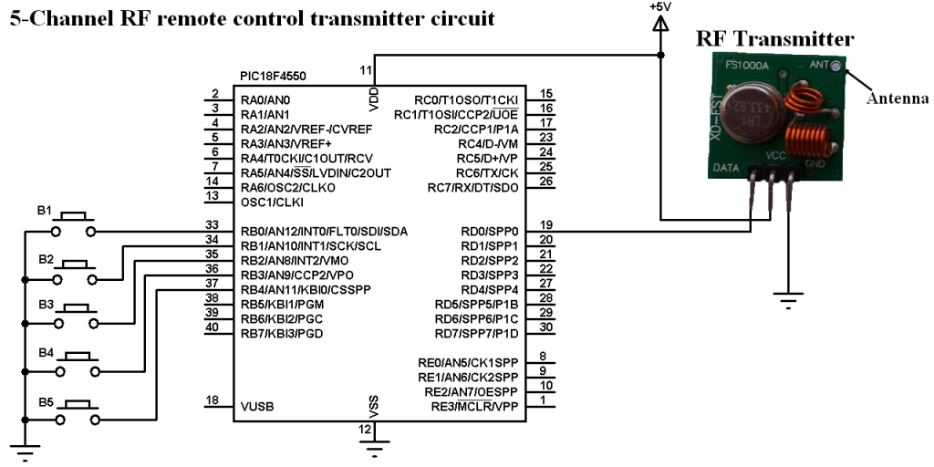
PIC18F4550 internal oscillator is used (8MHz) and MCLR is disabled.
RF Transmitter using PIC18F4550 CCS C code:
The following C code is the full code used for the transmitter circuit microcontroller which is written with CCS PIC C compiler version 5.0.51.
1 2 3 4 5 6 7 8 9 10 11 12 13 14 15 16 17 18 19 20 21 22 23 24 25 26 27 28 29 30 31 32 33 34 35 36 37 38 39 40 41 42 43 44 45 46 47 48 49 50 51 52 53 54 55 56 57 58 59 60 61 62 63 64 65 66 67 68 69 70 | // 5-Channel RF remote control using PIC18F4550 transmitter CCS C code #include <18F4550.h> #fuses NOMCLR INTRC_IO #use delay(clock = 8000000) #use fast_io(B) #use fast_io(D) void send_signal(unsigned int32 number){ int8 i; // Send 9ms pulse output_high(PIN_D0); delay_ms(9); // Send 4.5ms space output_low(PIN_D0); delay_us(4500); // Send data for(i = 0; i < 32; i++){ // If bit is 1 send 560us pulse and 1680us space if(bit_test(number, 31 - i)){ output_high(PIN_D0); delay_us(560); output_low(PIN_D0); delay_us(1680); } // If bit is 0 send 560us pulse and 560us space else{ output_high(PIN_D0); delay_us(560); output_low(PIN_D0); delay_us(560); } } // Send end bit output_high(PIN_D0); delay_us(560); output_low(PIN_D0); delay_us(560); } void main(){ setup_oscillator(OSC_8MHZ); // Set internal oscillator to 8MHz setup_adc_ports(NO_ANALOGS); // Configure AN pins as digital output_b(0); // PORTB initial state set_tris_b(0x1F); // Configure RB0-to-RB4 as inputs port_b_pullups(TRUE); // Enable PORTB internal pull-ips output_d(0); // PORTD initial state set_tris_d(0); // Configure PORTD pins as outputs while(TRUE){ while(!input(PIN_B0)){ send_signal(0x40BF00FF); delay_ms(500); } while(!input(PIN_B1)){ send_signal(0x40BF807F); delay_ms(500); } while(!input(PIN_B2)){ send_signal(0x40BF40BF); delay_ms(500); } while(!input(PIN_B3)){ send_signal(0x40BF20DF); delay_ms(500); } while(!input(PIN_B4)){ send_signal(0x40BFA05F); delay_ms(500); } } } |
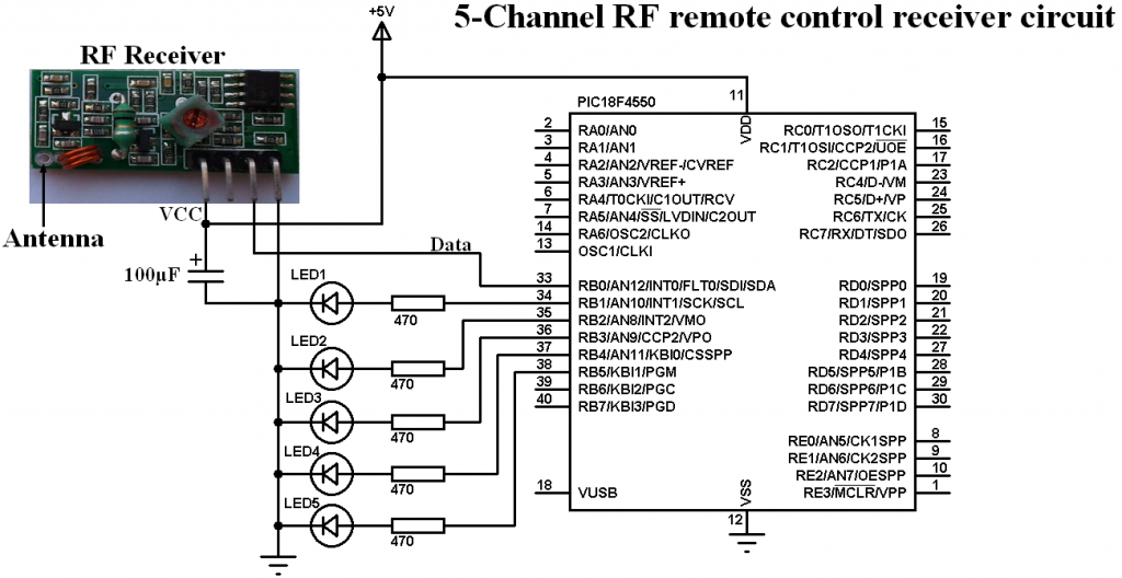
RF Receiver circuit:
Receiver circuit schematic diagram is shown below.
PIC18F4550 internal oscillator is used (8MHz) and MCLR is disabled.
In the receiver circuit there are 5 LEDs, each LED is controlled by one pushbutton on the transmitter circuit. The RF receiver receives RF signals transmitted from the RF transmitter on the transmitter circuit.
RF Receiver using PIC18F4550 CCS C code:
The NEC message has 32 bits which are divided into address (16 bits), command (8 bits) and inverted command (8 bits).
The microcontroller waits until the RF receiver receives an RF signal which makes RB0 goes from logic 0 to logic 1 and the command used is:
while(!input(PIN_B0));
After that a function named remote_read() is called, this function checks if the received signal has NEC protocol form all the time with a resolution of 10us then returns the received code.
1 2 3 4 5 6 7 8 9 10 11 12 13 14 15 16 17 18 19 20 21 22 23 24 25 26 27 28 29 30 31 32 33 34 35 36 37 38 39 40 41 42 43 44 45 46 47 48 49 50 51 52 53 54 55 56 57 58 59 60 61 62 63 64 65 66 | // 5-Channel RF remote control using PIC18F4550 receiver CCS C code #include <18F4550.h> #fuses NOMCLR INTRC_IO #use delay(clock = 8000000) #use fast_io(B) unsigned int32 remote_code; short remote_read(){ int8 i; unsigned int16 count = 0; // Check 9ms pulse (remote control sends logic high) while((input(PIN_B0) == 1) && (count < 600)){ count++; delay_us(10);} if( (count > 599) || (count < 500)) // NEC protocol? return FALSE; count = 0; // Check 4.5ms space (remote control sends logic low) while((input(PIN_B0) == 0) && (count < 300)){ count++; delay_us(10);} if( (count > 299) || (count < 220)) // NEC protocol? return FALSE; // Read message (32 bits) for(i = 0; i < 32; i++){ count = 0; while((input(PIN_B0) == 1) && (count < 45)){ count++; delay_us(10);} if( (count > 44) || (count < 25)) // NEC protocol? return FALSE; count = 0; while((input(PIN_B0) == 0) && (count < 120)){ count++; delay_us(10);} if( (count > 119) || (count < 25)) // NEC protocol? return FALSE; if( count > 60) // If space width > 1ms bit_set(remote_code, (31 - i)); // Write 1 to bit (31 - i) else // If space width < 1ms bit_clear(remote_code, (31 - i)); // Write 0 to bit (31 - i) } return TRUE; } void main(){ setup_oscillator(OSC_8MHZ); // Set internal oscillator to 8MHz setup_adc_ports(NO_ANALOGS); // Configure AN pins as digital output_b(0); // PORTB initial state set_tris_b(1); // Configure RB0 as digital input pin while(TRUE){ while(!input(PIN_B0)); // Wait until RB0 pin goes high if(remote_read()){ if(remote_code == 0x40BF00FF) output_toggle(PIN_B1); if(remote_code == 0x40BF807F) output_toggle(PIN_B2); if(remote_code == 0x40BF40BF) output_toggle(PIN_B3); if(remote_code == 0x40BF20DF) output_toggle(PIN_B4); if(remote_code == 0x40BFA05F) output_toggle(PIN_B5); } } } |
5-Channel RF remote control using PIC18F4550 microcontroller video:
The following video shows a prototype hardware circuit for this project.
In this video I used PORTD instead of PORTB for the 5 outputs of the receiver circuit.
Reference:
http://www.sbprojects.com/


