This Arduino project shows how to build a temperature data logger using SD card, DS18B20 digital temperature sensor and DS3231 real time clock board.
The Arduino reads temperature from the DS18B20 sensor and saves them (with date and time) to a text file stored on the SD card. The DS3231 real time clock chip is used to get time and date information.
Time, date and temperature values are displayed on 20×4 LCD screen and sent to PC serial monitor.
To see how to interface the Arduino with SD card, visit the following post:
Arduino and SD card example – Read and write files
To see how to interface Arduino with DS18B20 sensor, take a look at this post:
Digital thermometer using Arduino and DS18B20 sensor
Hardware Required:
This is a list of all components required to build this project.
- Arduino UNO board —-> Atmega328P datasheet
- micro SD card with FAT16 or FAT32 file system
- micro SD card module
- 20×4 LCD screen
- DS18B20 temperature sensor —-> datasheet
- DS3231 module —-> DS3231 datasheet
- 4.7k ohm resistor
- 330 ohm resistor
- 2 x push button
- 10k ohm variable resistor or potentiometer
- 3V coin cell battery
- Breadboard
- Jumper wires

Arduino temperature data logger with SD card circuit:
The image below shows project hardware circuit diagram.
In this project I used micro SD card module, this module is supplied from circuit 5V source that comes from the Arduino UNO board. This module contains AMS1117-3V3 voltage regulator which is used to supply the SD card with 3.3V. Also this module contains an IC which is 74LVC125A and it’s used as level translator (from 5V to 3.3V).
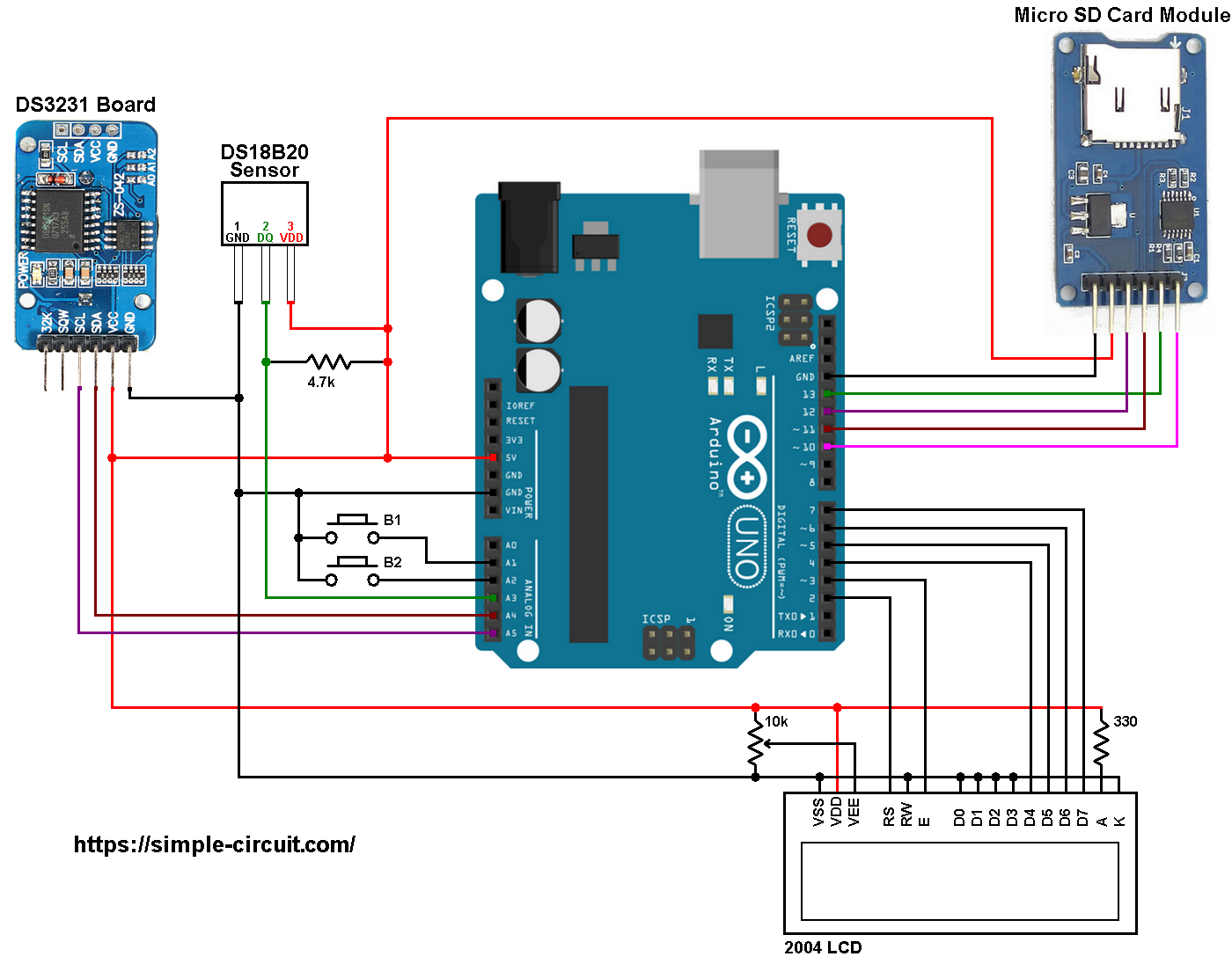
The microSD card module is connected to the Arduino as follows (from left to right):
The first pin of the micro SD card module (GND) is connected to Arduino GND.
The second pin of the micro SD card module (VCC) is connected to Arduino 5V.
The third pin of the micro SD card module (MISO) is connected to Arduino digital pin 12.
The fourth pin of the micro SD card module (MOSI) is connected to Arduino digital pin 11.
The fifth pin of the micro SD card module (SCK) is connected to Arduino digital pin 13.
The last pin of the micro SD card module (CS) is connected to Arduino digital pin 10.
The digital pins 10, 11, 12 and 13 are hardware SPI module pins of ATmega328P microcontroller (Arduino UNO microcontroller).
The DS3231 RTC module SDA (serial data) and SCL (serial clock) pins are respectively connected to Arduino A4 and A5 pins (ATmega328P hardware I2C module pins).
VCC is connected to Arduino 5V and GND is connected to Arduino GND.
The DS18B20 sensor has 3 pins (from right to left): VCC (or VDD), data and GND where:
VCC (VDD): sensor power supply pin, connected to Arduino 5V pin,
data pin: connected to Arduino analog pin 3 (A3) and
GND: connected to Arduino GND pin.
A pull-up resistor of 4.7k ohm is required because the DS18B20 output is open drain.
The 20×4 LCD screen (4 rows and 20 columns) is used to display time, date and temperature where:
RS —> Arduino digital pin 2
E —> Arduino digital pin 3
D4 —> Arduino digital pin 4
D5 —> Arduino digital pin 5
D6 —> Arduino digital pin 6
D7 —> Arduino digital pin 7
VSS, RW, D0, D1, D2, D3 and K are connected to Arduino ground,
VEE to the 10k ohm variable resistor (or potentiometer) output,
VDD to Arduino 5V and A to Arduino 5V through 330 ohm resistor.
VEE pin is used to control the contrast of the LCD. A (anode) and K (cathode) are the back light LED pins.
In the circuit there are two push buttons: B1 and B2, they are respectively connected to Arduino analog pins 1 (A1) and 2 (A2), these buttons are used to set time and date of the real time clock.
Arduino temperature data logger with SD card code:
To be able to compile project Arduino code with no error, a driver (library) for the DS3231 RTC is required, download link is below:
Adafruit RTC library —-> direct link
After the download, go to Arduino IDE —> Sketch —> Include Library —> Add .ZIP Library … and browse for the .zip file (previously downloaded).
Programming hints:
There are 3 libraries included in the Arduino code as shown below.
The first library is for the SD card,
the 2nd one is for the LCD display,
and the last library is for the DS3231 RTC.
1 2 3 | #include <SD.h> // include Arduino SD library #include <LiquidCrystal.h> // include Arduino LCD library #include <RTClib.h> // include Adafruit RTC library |
The connection of the 2 push buttons and the DS18B20 sensor data pin are defined in the code as:
1 2 3 4 5 | // buttons definition #define button1 A1 // button B1 is connected to Arduino pin A1 #define button2 A2 // button B2 is connected to Arduino pin A2 // define DS18B20 data pin #define DS18B20_PIN A3 |
The microcontroller reads temperature values from the DS18B20 sensor and saves them (with time and date) to the SD card every 10 seconds, for that I used the following if condition:
1 | if( (now.second() % 10 == 0) && (p_second != now.second()) ) |
Functions used in the code:
SD Card functions:
SD.begin(): this function initializes the SD card as well as the file system (FAT16 or FAT32), it returns 1 (true) if OK and 0 (false) if error.
SD.exists(“Log.txt”): tests whether the file “Log.txt” exists on the SD card, returns 1 if the file already exists and 0 if not.
SD.open(“Log.txt”, FILE_WRITE): opens the file “Log.txt” and moves the cursor to the end of the file. This function will create the file if it doesn’t already exist. Returns 0 if error.
dataLog.close(): closes the file associated with dataLog.
DS3231 Functions:
bool debounce (): this function is for button B1 debounce, returns 1 if button is debounced.
void RTC_display(): displays day of the week, date and time on the display.
byte edit(byte parameter): this function is for setting the real time clock, returns the edited parameter.
DS18B20 Functions:
bool ds18b20_start(): used to know if the DS18B20 sensor is correctly connected to the circuit, returns 1 if OK and 0 if error.
ds18b20_write_bit(bool value): writes (sends) 1 bit to the DS18B20 sensor, the bit is ‘value‘ which may be 1 or 0.
ds18b20_write_byte(byte value): writes 1 byte (8 bits) to the DS18B20 sensor, this function is based on the previous function. This function writes LSB first.
bool ds18b20_read_bit(void): reads 1 bit from the DS18B20 sensor, returns the read value (1 or 0).
byte ds18b20_read_byte(void): reads 1 byte from the DS18B20 sensor, this function is based on the previous function. This function reads LSB first.
bool ds18b20_read(int *raw_temp_value): reads the temperature raw data which is 16-bit long (two 8-bit registers), the data is stored in the variable raw_temp_value, returns 1 if OK and 0 if error.
The value of the temperature in degree Celsius is equal to the raw value divided by 16 (in case of 12-bit resolution). The default resolution of the DS18B20 is 12 bits ( ==> thermometer resolution = 0.0625°C).
Full Arduino code:
1 2 3 4 5 6 7 8 9 10 11 12 13 14 15 16 17 18 19 20 21 22 23 24 25 26 27 28 29 30 31 32 33 34 35 36 37 38 39 40 41 42 43 44 45 46 47 48 49 50 51 52 53 54 55 56 57 58 59 60 61 62 63 64 65 66 67 68 69 70 71 72 73 74 75 76 77 78 79 80 81 82 83 84 85 86 87 88 89 90 91 92 93 94 95 96 97 98 99 100 101 102 103 104 105 106 107 108 109 110 111 112 113 114 115 116 117 118 119 120 121 122 123 124 125 126 127 128 129 130 131 132 133 134 135 136 137 138 139 140 141 142 143 144 145 146 147 148 149 150 151 152 153 154 155 156 157 158 159 160 161 162 163 164 165 166 167 168 169 170 171 172 173 174 175 176 177 178 179 180 181 182 183 184 185 186 187 188 189 190 191 192 193 194 195 196 197 198 199 200 201 202 203 204 205 206 207 208 209 210 211 212 213 214 215 216 217 218 219 220 221 222 223 224 225 226 227 228 229 230 231 232 233 234 235 236 237 238 239 240 241 242 243 244 245 246 247 248 249 250 251 252 253 254 255 256 257 258 259 260 261 262 263 264 265 266 267 268 269 270 271 272 273 274 275 276 277 278 279 280 281 282 283 284 285 286 287 288 289 290 291 292 293 294 295 296 297 298 299 300 301 302 303 304 305 306 307 308 309 | /* Arduino temperature logger with SD card, DS18B20 sensor and DS3231 (DS1307) RTC. * Time, date and temperature are displayed on 20x4 LCD. * This is a free software with NO WARRANTY. * http://simple-circuit.com/ */ #include <SD.h> // include Arduino SD library #include <LiquidCrystal.h> // include Arduino LCD library #include <RTClib.h> // include Adafruit RTC library // LCD module connections (RS, E, D4, D5, D6, D7) LiquidCrystal lcd(2, 3, 4, 5, 6, 7); // initialize RTC library RTC_DS3231 rtc; DateTime now; // buttons definition #define button1 A1 // button B1 is connected to Arduino pin A1 #define button2 A2 // button B2 is connected to Arduino pin A2 // define DS18B20 data pin #define DS18B20_PIN A3 File dataLog; boolean sd_ok = 0; void setup() { pinMode(button1, INPUT_PULLUP); pinMode(button2, INPUT_PULLUP); rtc.begin(); // initialize RTC chip lcd.begin(20, 4); // initialize LCD module lcd.setCursor(0, 3); // move cursor to column 0, row 3 (last row) lcd.print("Temp:"); // open serial communications and wait for port to open: Serial.begin(9600); Serial.print("Initializing SD card..."); // initialize the SD card if ( !SD.begin() ) Serial.println("initialization failed!"); // initialization error else { // initialization OK sd_ok = 1; Serial.println("initialization done."); if( SD.exists("Log.txt") == 0 ) // test if file with name 'Log.txt' already exists { // create a text file named 'Log.txt' Serial.print("\r\nCreate 'Log.txt' file ... "); dataLog = SD.open("Log.txt", FILE_WRITE); // create (&open) file Log.txt if(dataLog) { // if the file opened okay, write to it: Serial.println("OK"); // write some texts to 'Log.txt' file dataLog.println(" DATE | TIME | TEMPERATURE"); dataLog.println("(dd-mm-yyyy)|(hh:mm:ss)|"); dataLog.close(); // close the file } else Serial.println("error creating file."); } } Serial.println("\r\n DATE | TIME | TEMPERATURE"); Serial.println("(dd-mm-yyyy)|(hh:mm:ss)|"); } // main loop void loop() { now = rtc.now(); // read current time and date from the RTC chip RTC_display(); // diaplay time & calendar if( !digitalRead(button1) ) // if B1 is pressed if( debounce() ) // call debounce function (make sure B1 is pressed) { while( debounce() ); // call debounce function (wait for B1 to be released) byte hour = edit( now.hour() ); // edit hours byte minute = edit( now.minute() ); // edit minutes byte day = edit( now.day() ); // edit date byte month = edit( now.month() ); // edit month byte year = edit( now.year() - 2000 ); // edit year // write time & date data to the RTC chip rtc.adjust(DateTime(2000 + year, month, day, hour, minute, 0)); while(debounce()); // call debounce function (wait for button B1 to be released) } static byte p_second; if( (now.second() % 10 == 0) && (p_second != now.second()) ) { // read & print temperature value from sensor every 10 seconds unsigned int ds18b20_temp; char buffer1[12], buffer2[26]; bool sensor_ok = 0; p_second = now.second(); if( ds18b20_read(&ds18b20_temp) ) { sensor_ok = 1; if (ds18b20_temp & 0x8000) // if temperature < 0 { ds18b20_temp = ~ds18b20_temp + 1; // change temperature value to positive form sprintf(buffer1, "-%02u.%04u%cC", (ds18b20_temp/16) % 100, (ds18b20_temp & 0x0F) * 625, 223); } else { // otherwise (temperature >= 0) if (ds18b20_temp/16 >= 100) // if temperature >= 100.0 °C sprintf(buffer1, "%03u.%04u%cC", ds18b20_temp/16, (ds18b20_temp & 0x0F) * 625, 223); else // otherwise ( 0 <= temperature < 100.0) sprintf(buffer1, " %02u.%04u%cC", ds18b20_temp/16, (ds18b20_temp & 0x0F) * 625, 223); } } else sprintf(buffer1, " ERROR "); lcd.setCursor(5, 3); lcd.print(buffer1); sprintf( buffer2, " %02u-%02u-%04u | %02u:%02u:%02u | ", now.day(), now.month(), now.year(), now.hour(), now.minute(), now.second() ); if(sensor_ok) { buffer1[8] = 194; // put degree symbol buffer1[9] = 176; buffer1[10] = 'C'; // put 'C' letter buffer1[11] = '\0'; // put string terminator } // print data on PC serial monitor Serial.print(buffer2); Serial.println(buffer1); // write data to SD card if(sd_ok) { // if the SD card was successfully initialized // open Log.txt file with write permission dataLog = SD.open("Log.txt", FILE_WRITE); dataLog.print( buffer2 ); dataLog.println( buffer1 ); dataLog.close(); // close the file } } delay(100); // wait 100ms } //////////////////////////////////////// RTC functions //////////////////////////////////////// void RTC_display() { char _buffer[17]; char dow_matrix[7][10] = {" SUNDAY ", " MONDAY ", " TUESDAY ", "WEDNESDAY", "THURSDAY ", " FRIDAY ", "SATURDAY "}; lcd.setCursor(4, 0); lcd.print( dow_matrix[now.dayOfTheWeek()] ); // print time sprintf( _buffer, "TIME: %02u:%02u:%02u", now.hour(), now.minute(), now.second() ); lcd.setCursor(0, 1); lcd.print(_buffer); // print date sprintf( _buffer, "DATE: %02u-%02u-%04u", now.day(), now.month(), now.year() ); lcd.setCursor(0, 2); lcd.print(_buffer); } byte edit(byte parameter) { static byte i = 0, y_pos, x_pos[5] = {6, 9, 6, 9, 14}; char text[3]; sprintf(text,"%02u", parameter); if(i < 2) y_pos = 1; else y_pos = 2; while( debounce() ); // call debounce function (wait for B1 to be released) while(true) { while( !digitalRead(button2) ) { // while B2 is pressed parameter++; if(i == 0 && parameter > 23) // if hours > 23 ==> hours = 0 parameter = 0; if(i == 1 && parameter > 59) // if minutes > 59 ==> minutes = 0 parameter = 0; if(i == 2 && parameter > 31) // if day > 31 ==> day = 1 parameter = 1; if(i == 3 && parameter > 12) // If month > 12 ==> month = 1 parameter = 1; if(i == 4 && parameter > 99) // If year > 99 ==> year = 0 parameter = 0; sprintf(text,"%02u", parameter); lcd.setCursor(x_pos[i], y_pos); lcd.print(text); delay(200); // wait 200ms } lcd.setCursor(x_pos[i], y_pos); lcd.print(" "); unsigned long previous_m = millis(); while( (millis() - previous_m < 250) && digitalRead(button1) && digitalRead(button2) ) ; lcd.setCursor(x_pos[i], y_pos); lcd.print(text); previous_m = millis(); while( (millis() - previous_m < 250) && digitalRead(button1) && digitalRead(button2) ) ; if(!digitalRead(button1)) { // if button B1 is pressed i = (i + 1) % 5; // increment 'i' for the next parameter return parameter; // return parameter value and exit } } } // a small function for button1 (B1) debounce bool debounce () { byte count = 0; for(byte i = 0; i < 5; i++) { if ( !digitalRead(button1) ) count++; delay(10); } if(count > 2) return 1; else return 0; } ////////////////////////////////////// end RTC functions ////////////////////////////////////// ////////////////////////////////// DS18B20 sensor functions /////////////////////////////////// bool ds18b20_start() { bool ret = 0; digitalWrite(DS18B20_PIN, LOW); // send reset pulse to the DS18B20 sensor pinMode(DS18B20_PIN, OUTPUT); delayMicroseconds(500); // wait 500 us pinMode(DS18B20_PIN, INPUT); delayMicroseconds(100); // wait to read the DS18B20 sensor response if (!digitalRead(DS18B20_PIN)) { ret = 1; // DS18B20 sensor is present delayMicroseconds(400); // wait 400 us } return(ret); } void ds18b20_write_bit(bool value) { digitalWrite(DS18B20_PIN, LOW); pinMode(DS18B20_PIN, OUTPUT); delayMicroseconds(2); digitalWrite(DS18B20_PIN, value); delayMicroseconds(80); pinMode(DS18B20_PIN, INPUT); delayMicroseconds(2); } void ds18b20_write_byte(byte value) { byte i; for(i = 0; i < 8; i++) ds18b20_write_bit(bitRead(value, i)); } bool ds18b20_read_bit(void) { bool value; digitalWrite(DS18B20_PIN, LOW); pinMode(DS18B20_PIN, OUTPUT); delayMicroseconds(2); pinMode(DS18B20_PIN, INPUT); delayMicroseconds(5); value = digitalRead(DS18B20_PIN); delayMicroseconds(100); return value; } byte ds18b20_read_byte(void) { byte i, value; for(i = 0; i < 8; i++) bitWrite(value, i, ds18b20_read_bit()); return value; } bool ds18b20_read(int *raw_temp_value) { if (!ds18b20_start()) // send start pulse return(0); ds18b20_write_byte(0xCC); // send skip ROM command ds18b20_write_byte(0x44); // send start conversion command while(ds18b20_read_byte() == 0); // wait for conversion complete if (!ds18b20_start()) // send start pulse return(0); // return 0 if error ds18b20_write_byte(0xCC); // send skip ROM command ds18b20_write_byte(0xBE); // send read command // read temperature LSB byte and store it on raw_temp_value LSB byte *raw_temp_value = ds18b20_read_byte(); // read temperature MSB byte and store it on raw_temp_value MSB byte *raw_temp_value |= (unsigned int)(ds18b20_read_byte() << 8); return(1); // OK --> return 1 } //////////////////////////////////// end DS18B20 functions //////////////////////////////////// // end of code. |
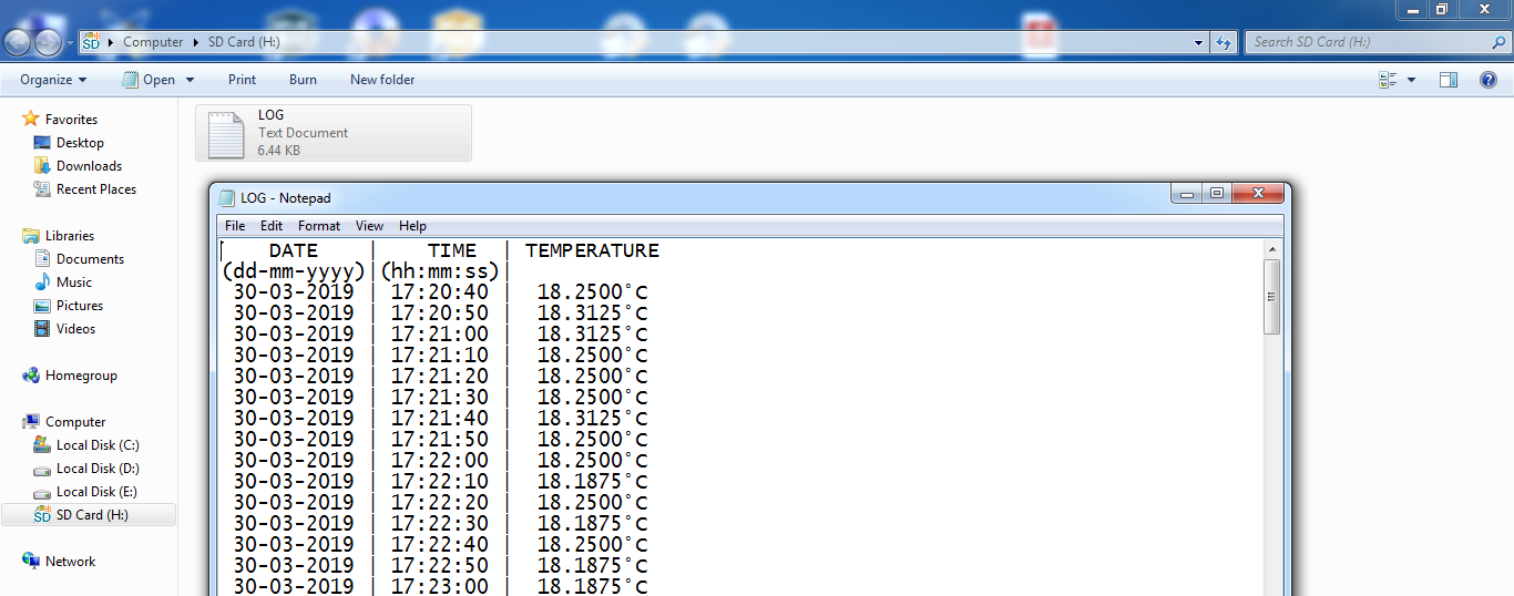
This project was tested in real hardware circuit using original Samsung microSD card with capacity of 32GB. The following image shows data logger file (Log.txt) created by the hardware circuit:
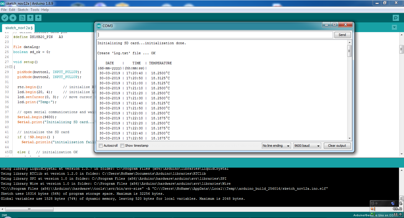
And the following one shows serial monitor output:
Proteus simulation:
This project could be simulated using Proteus software, the following video shows the result of the simulation.
Note that Proteus simulation circuit is not the same as real hardware circuit, project hardware circuit is shown above.
Proteus simulation file download link:
Arduino temperature datalogger
SD Card image file (FAT16_SD.ima) download link:
SD Card FAT16 image


How can I change the time between measurements from 10 seconds to 2 minutes?
Hello,
Does anyone know what could be the reason that the temperature value is not shown on the display nor in the serial monitor? everything else seems to be working correctly.
It only shows Temp: in the display and TEMPERATURE in the serial monitor.
Sorry folks, I used the wrong RTCLib library. Now it works perfectly.
Hi James,
Your welcome. We are all beginners, so we must help each other. It is correct for this program. When you first run, you must open the serial monitor to see if sd card is okay or not.
Don’t forget please, While writing codes, serial monitor is using for printing some knowledge on monitor screen instead of lcd, led display, etc. We can just write codes without using circuit.
Code line 42 is for initializing sd card and line 43 is to show result of sd card on serial monitor. For example, i will change the codes later for my project. I will rewrite “serial.print” commands to “print” commands to see on lcd / ST7735 display while first running (initializing sd card) stand alone.
I hope i helped you. Best regards.
Hi James,
I think you don’t need to connect your project to the computer, just connect extra power supply and run your project. Serial monitor is just helping you. Also you can convert serial monitor print commands to lcd print commands and you can use without serial monitor.
Hi Onder. Thanks so much for your help. I already had an external supply connected. The problem was me not
understanding the process. It appears that I need to open the serial monitor to initialise the sd card. After that I can close the monitor and disconnect the project from my laptop and it will continue to record data as a stand alone unit.
Is that correct. Regards James(Jim)
Hi. Good project. However to write data to the SD card the project must be connected
to my computer and the serial monitor must be open. Is there a code change that
would fix this? Cheers.
I get error in the code help me pls :
C:\Users\marou\Desktop\sketch_apr17a\sketch_apr17a.ino: In function ‘void loop()’:
C:\Users\marou\Desktop\sketch_apr17a\sketch_apr17a.ino:92:22: warning: invalid conversion from ‘unsigned int*’ to ‘int*’ [-fpermissive]
if( ds18b20_read(&ds18b20_temp) )
^~~~~~~~~~~~~
C:\Users\marou\Desktop\sketch_apr17a\sketch_apr17a.ino:282:6: note: initializing argument 1 of ‘bool ds18b20_read(int*)’
bool ds18b20_read(int *raw_temp_value)
^~~~~~~~~~~~
this project opened my horizons.
thank you so much.
i tested it with this 8.9 sp2. it works fine
I figured out how to display degrees F . All it took was some time to understand. I am a beginner still.
(ds18b20_temp/16)*9/5+32 buffer1[10] = ‘C’; // put ‘C’ letter change the C to F
Is it possible to read temperature data from 100k ntc thermistor? If it is possible from 3 different temp reading?
Hi JM,
Unfortunately I did not get a reply. Looks like we have to learn programming.ouselves.
I build it and it works like charm.
But I would like to connect 3 temp sensors. How do I change the sketch so it writes the values of 3 sensors to the SD card?
I don’t mind if the display only displays the value of one sensor.
I’m new to programming.
Henk
This is cool and fun to build. I like paling with stats and graphs and am seeing if the temperature in my apartment is conducive to brewing (fermenting) beer by logging the temperature inside a 5 gallon bottle of water over time. I am using a DS18B20 Temperature Sensor Waterproof Digital Thermal Probe Sensor. How can I program this for degrees Fahrenheit ?
Hi Henk
I have the same problem (better to have 5 but can deal with only 3)
Did you get an answer ?
how to edit date and time in this program
You can set time and date using the 2 push buttons, watch simulation video to see how it works!
hello, this code is absolutely awesome but the time and date being saved doesn’t match the actual time and date. please help me solve this probem