This tutorial shows how to make a simple real time clock & calendar using PIC18F46K22 microcontroller and DS1307 RTC chip.
In this project time and date are displayed on SSD1306 OLED screen (128×64 pixel) and they could be set with two push buttons connected to the PIC18F46K22.
MikroC PRO for PIC compiler is used in this project.
In this project the SSD1306 OLED is configured to work in I2C mode, make sure that your display is configured to work in I2C mode, some displays need jumper placing or some soldering.
To see how to interface PIC18F46K22 MCU with SSD1306 OLED display (I2C mode), take a look at the following project:
Interfacing PIC18F46K22 with SSD1306 OLED display | mikroC Projects
Hardware Required:
- PIC18F46K22 microcontroller —-> datasheet
- SSD1306 OLED display
- DS1307 RTC —-> datasheet
- 32.768 kHz crystal oscillator
- 2 x 10k ohm resistor
- 2 x push button
- 3V coin cell battery
- 5V power source
- Breadboard
- Jumper wires
PIC18F46K22 with SSD1306 OLED and DS1307 RTC circuit:
The following image shows project circuit schematic diagram.
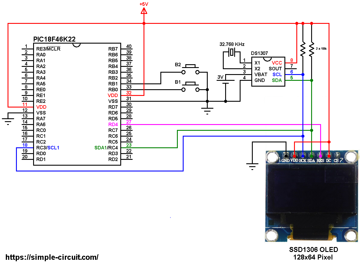
All the grounded terminals are connected together.
The PIC18F46K22 microcontroller has 2 hardware I2C modules (MSSP1 and MSSP2 modules).
In this project I2C1 module is used with SDA1 on pin RC4 (#23) and SCL1 on pin RC3 (#18). The SDA1 pin of the MCU is connected to the SDA pin of the display and the SCL1 pin of the MCU is connected to the SCL pin of the display.
The reset pin of the display is connected to pin RD4 (#27) of the microcontroller.
The SSD1306 OLED display DC pin is connected to VDD which means I2C slave address of the device is 0x7A.
The SSD1306 OLED and the DS1307 RTC share the same I2C bus, SCL and SDA pins of the DS1307 RTC are also connected to SCL1 and SDA1 pins of the PIC18F46K22.
The two push buttons in the circuit are used to set time and date of the real time clock, button 1 (B1) is connected to RB0 pin (#33) and button 2 (B2) is connected to RB1 pin (#34).
In this project the PIC18F46K22 microcontroller runs with its internal oscillator @ 16 MHz, MCLR pin is configured as an input pin.
PIC18F46K22 with SSD1306 OLED and DS1307 RTC C code:
The following C code is for mikroC PRO for PIC compiler, it was tested with version 7.2.0.
To be able to compile the C code below with no error, a driver for the SSD1306 OLED display is required, its full name (with extension) is SSD1306OLED.C, download link is the one below:
SSD1306 OLED mikroC library
for more information about this driver, visit the following post:
SSD1306 OLED display library for mikroC compiler | mikroC Projects
Also, another library for the DS1307 RTC is required, its full name (with extension) is: DS1307.C, download link is the one below:
DS1307 mikroC library
and for more details about it, visit this topic:
DS1307 RTC Library for mikroC Compiler | mikroC Projects
after the download of the 2 library files, add both of them to mikroC project folder.
The connection of the two push buttons and the SSD1306 OED reset pin are defined in the C code as shown below:
1 2 3 4 5 6 7 | // button definitions #define button1 RB0_bit // button B1 is connected to RB0 pin #define button2 RB1_bit // button B2 is connected to RB1 pin // SSD1306 OLED reset pin definition (if available) #define SSD1306_RST RD4_bit #define SSD1306_RST_DIR TRISD4_bit |
The drivers of the SSD1306 OLED and the DS1307 RTC are included in the code using the 2 lines below:
1 2 | #include <SSD1306OLED.c> // include SSD1306 OLED display driver source code #include <DS1307.c> // include DS1307 RTC driver source file |
Functions used in the code:
char debounce (): this function is for button B1 debounce, returns 1 if button is debounced.
void dow_print(): displays day of the week (Monday, Tuesday …) on the LCD.
void rtc_print(): displays time, date and day of the week on the LCD. This function calls the previous one for displaying the day of the week.
void wait(): this function is just a delay of 500 ms except that it can be interrupted by the two push buttons (B1 and B2). In this function Timer0 module is used to count the 500 milliseconds, it is used as 16-bit timer with prescaler = 16 (==> 1 tick every 8 microseconds ==> 62500 x 8 = 500000 us = 500 ms).
char edit(char x_pos, char y_pos, char parameter): this function is for setting the real time clock, returns the edited parameter.
Rest of code is described through comments.
Full mikroC code:
1 2 3 4 5 6 7 8 9 10 11 12 13 14 15 16 17 18 19 20 21 22 23 24 25 26 27 28 29 30 31 32 33 34 35 36 37 38 39 40 41 42 43 44 45 46 47 48 49 50 51 52 53 54 55 56 57 58 59 60 61 62 63 64 65 66 67 68 69 70 71 72 73 74 75 76 77 78 79 80 81 82 83 84 85 86 87 88 89 90 91 92 93 94 95 96 97 98 99 100 101 102 103 104 105 106 107 108 109 110 111 112 113 114 115 116 117 118 119 120 121 122 123 124 125 126 127 128 129 130 131 132 133 134 135 136 137 138 139 140 141 142 143 144 145 146 147 148 149 150 151 152 153 154 155 156 157 158 159 160 161 162 163 164 165 166 167 168 169 170 171 172 173 174 175 176 177 178 179 180 181 182 183 184 185 186 187 188 189 190 191 192 193 194 195 196 197 198 199 200 201 202 203 204 205 206 207 208 209 210 211 212 213 214 215 216 217 218 219 220 221 222 223 224 225 226 227 228 229 230 | /************************************************************************************** Interfacing PIC18F46K22 microcontroller with SSD1306 OLED (128x64 Pixel) and DS1307 RTC. C Code for mikroC PRO for PIC compiler. Internal oscillator used @ 16MHz Configuration words: CONFIG1H = 0x0028 CONFIG2L = 0x0018 CONFIG2H = 0x003C CONFIG3H = 0x0037 CONFIG4L = 0x0081 CONFIG5L = 0x000F CONFIG5H = 0x00C0 CONFIG6L = 0x000F CONFIG6H = 0x00E0 CONFIG7L = 0x000F CONFIG7H = 0x0040 This is a free software with NO WARRANTY. http://simple-circuit.com/ ***************************************************************************************/ // button definitions #define button1 RB0_bit // button B1 is connected to RB0 pin #define button2 RB1_bit // button B2 is connected to RB1 pin // SSD1306 OLED reset pin definition (if available) #define SSD1306_RST RD4_bit #define SSD1306_RST_DIR TRISD4_bit #include <SSD1306OLED.c> // include SSD1306 OLED display driver source code #include <DS1307.c> // include DS1307 RTC driver source file RTC_Time *mytime; // DS1307 library variable // a small function for button1 (B1) debounce char debounce() { char m, count = 0; for(m = 0; m < 5; m++) { if ( !button1 ) count++; delay_ms(10); } if(count > 2) return 1; else return 0; } // interrupted delay void wait() { unsigned int TMR0_value = 0; TMR0L = TMR0H = 0; // rest Timer0 low and high registers while( (TMR0_value < 62500L) && button1 && button2 ) TMR0_value = (TMR0H << 8) | TMR0L; } char edit(char x_pos, char y_pos, char parameter) { static i = 0; char buffer[5]; while(debounce()); // call debounce function (wait for B1 to be released) SSD1306_GotoXY(x_pos, y_pos); sprinti(buffer, "%02u\b\b", (int)parameter); while(1) { while( !button2 ) // while button2 is pressed { parameter++; if(i == 0 && parameter > 31) // if day > 31 ==> day = 1 parameter = 1; if(i == 1 && parameter > 12) // if month > 12 ==> month = 1 parameter = 1; if(i == 2 && parameter > 99) // if year > 99 ==> year = 0 parameter = 0; if(i == 3 && parameter > 23) // if hours > 23 ==> hours = 0 parameter = 0; if(i == 4 && parameter > 59) // if minutes > 59 ==> minutes = 0 parameter = 0; sprinti(buffer, "%02u\b\b", (int)parameter); SSD1306_Print(buffer); SSD1306_Display(); delay_ms(200); } SSD1306_Print(" \b\b"); SSD1306_Display(); wait(); SSD1306_Print(buffer); SSD1306_Display(); wait(); if(!button1) // if button B1 is pressed { i = (i + 1) % 5; // increment 'i' for the next parameter return parameter; // return parameter value and exit } } } void dow_print() { switch(mytime->dow) { case SUNDAY: SSD1306_GotoXY(17, 0); SSD1306_Print(" SUNDAY "); break; case MONDAY: SSD1306_GotoXY(17, 0); SSD1306_Print(" MONDAY "); break; case TUESDAY: SSD1306_GotoXY(11, 0); SSD1306_Print(" TUESDAY "); break; case WEDNESDAY: SSD1306_GotoXY(11, 0); SSD1306_Print("WEDNESDAY"); break; case THURSDAY: SSD1306_GotoXY(5, 0); SSD1306_Print(" THURSDAY "); break; case FRIDAY: SSD1306_GotoXY(17, 0); SSD1306_Print(" FRIDAY "); break; default: SSD1306_GotoXY(5, 0); SSD1306_Print(" SATURDAY"); break; } // now update the displayed screen SSD1306_Display(); } void rtc_print() { char buffer[11]; // print date SSD1306_GotoXY(4, 25); sprinti(buffer, "%02u-%02u-20%02u", (int)mytime->day, (int)mytime->month, (int)mytime->year); SSD1306_Print(buffer); // print time SSD1306_GotoXY(16, 50); sprinti(buffer, "%02u:%02u:%02u", (int)mytime->hours, (int)mytime->minutes, (int)mytime->seconds); SSD1306_Print(buffer); // print day of the week dow_print(); } // main function void main() { OSCCON = 0x70; // set internal oscillator to 16MHz ANSELB = 0; // configure all PORTB pins as digital ANSELC = 0; // configure all PORTC pins as digital ANSELD = 0; // configure all PORTD pins as digital T0CON = 0x04; // configure Timer0 module (16-bit timer & prescaler = 32) // enable RB0 and RB1 internal pull ups RBPU_bit = 0; // clear RBPU bit (INTCON2.7) WPUB = 0x03; // WPUB register = 0b00000011 I2C1_Init(100000); // initialize I2C communication with clock frequency of 100kHz delay_ms(1000); // wait a second // initialize the SSD1306 OLED with an I2C addr = 0x7A (default address) SSD1306_Begin(SSD1306_SWITCHCAPVCC, SSD1306_I2C_ADDRESS); SSD1306_ClearDisplay(); // clear the display buffer SSD1306_SetTextWrap(false); // disable text wrap SSD1306_TextSize(2); // set text size to 2 if( OSC_Status() == false ) // if RTC oscillator is disabled OSC_Enable(); // enable it while(1) { // read current time and date from the RTC chip mytime = RTC_Get(); // print all data rtc_print(); if( !button1 ) // if button B1 is pressed if( debounce() ) // call debounce function (make sure if B1 is pressed) { while( debounce() ); // call debounce function (wait for button B1 to be released) TMR0ON_bit = 1; // enable Timer0 module while(1) { while( !button2 ) // if button B2 button is pressed { mytime->dow++; if(mytime->dow > SATURDAY) mytime->dow = SUNDAY; dow_print(); // print week day delay_ms(500); // wait half a second } SSD1306_FillRect(11, 0, 106, 14); SSD1306_Display(); wait(); // call wait() function dow_print(); // print week day wait(); // call wait() function if( !button1 ) // if button B1 is pressed break; } mytime->day = edit(4, 25, mytime->day); // edit day (day of month) mytime->month = edit(40, 25, mytime->month); // edit month mytime->year = edit(100, 25, mytime->year); // edit year mytime->hours = edit(16, 50, mytime->hours); // edit hours mytime->minutes = edit(52, 50, mytime->minutes); // edit minutes mytime->seconds = 0; // reset seconds TMR0ON_bit = 0; // disable Timer0 module while(debounce()); // call debounce function (wait for button B1 to be released) // write data to the RTC chip RTC_Set(mytime); } // end 'if( debounce() )' delay_ms(100); // wait 100 milliseconds } } // end of code. |
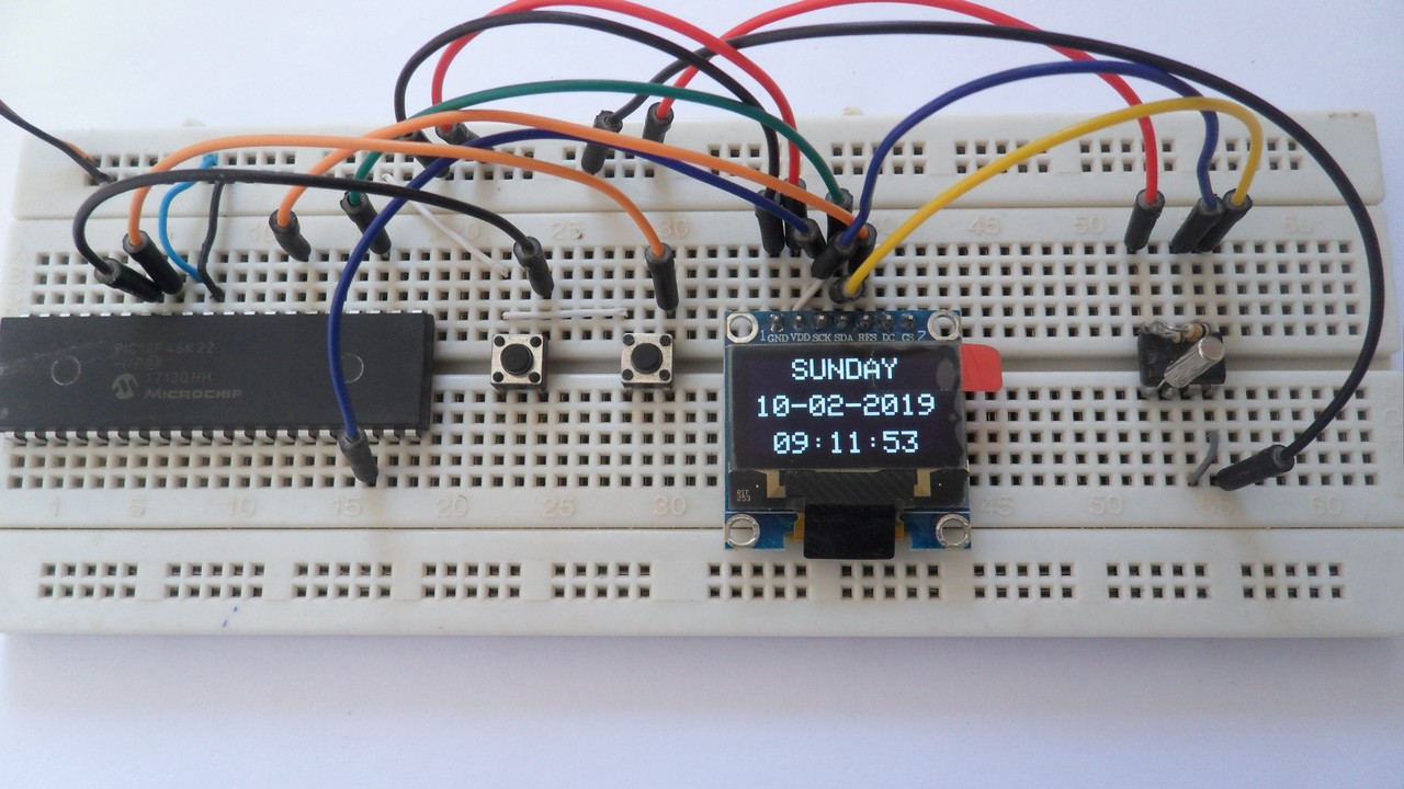
The following picture shows a protoboard circuit of the project: