This post shows how to build real time clock & calendar with 2 alarm functions and chip temperature monitor using PIC18F46K22 microcontroller and DS3231 RTC chip.
In this project time, date and alarms are displayed on SSD1306 OLED screen (128×64 pixel) and they could be set from three push buttons connected to the PIC18F46K22.
MikroC PRO for PIC compiler is used in this project.
The DS3231 RTC has built-in two alarm functions and temperature sensor with resolution of 0.25 °C and accuracy of ±3 °C. Chip temperature also will be displayed on the SSD1306 OLED.
In this project the SSD1306 OLED is configured to work in I2C mode, make sure that your display is configured to work in I2C mode, some displays need jumper placing or some soldering.
To see how to interface PIC18F46K22 MCU with SSD1306 OLED display (I2C mode), take a look at the following project:
Interfacing PIC18F46K22 with SSD1306 OLED display | mikroC Projects
Hardware Required:
- PIC18F46K22 microcontroller —-> datasheet
- SSD1306 OLED display
- DS3231 board —-> DS3231 datasheet
- 3 x push button
- 330 ohm resistor
- LED
- 3V coin cell battery
- 5V power source
- Breadboard
- Jumper wires
PIC18F46K22 with DS3231 RTC and SSD1306 OLED circuit:
The following image shows project circuit schematic diagram.
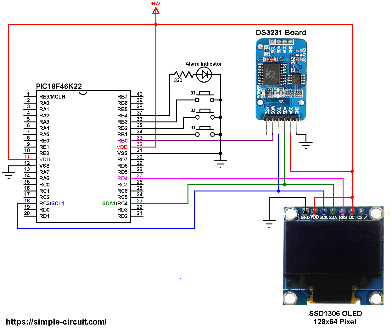
All the grounded terminals are connected together.
The PIC18F46K22 microcontroller has 2 hardware I2C modules (MSSP1 and MSSP2 modules).
In this project I2C1 module is used with SDA1 on pin RC4 (#23) and SCL1 on pin RC3 (#18). The SDA1 pin of the MCU is connected to the SDA pin of the display and the SCL1 pin of the MCU is connected to the SCL pin of the display.
The reset pin of the display is connected to pin RD4 (#27) of the microcontroller.
The SSD1306 OLED display DC pin is connected to VDD which means I2C slave address of the device is 0x7A.
The SSD1306 OLED and the DS3231 RTC share the same I2C bus, SCL and SDA pins of the DS3231 board are also connected to SCL1 and SDA1 pins of the PIC18F46K22.
In the circuit there are 3 push buttons: B1, B2 and B3. These buttons are used to set time, date and alarms. Time and date are set with B1 and B2 where button B1 selects time or date parameter (time parameters: hours and minutes; date parameters: day of the week, date, month and year) and B2 increments the selected parameter. Buttons B3 and B2 set alarm 1 and alarm 2 parameters (hours, minutes and ON/OFF), button B3 selects the parameter and B2 increments the selected parameter.
Also, there is an LED connected to PIC18F46K22 pin RB4 (#37), this LED is used as an alarm indicator (alarm 1 and alarm 2), so if there is an alarm, the DS3231 pulls down the INT line (RB0) which interrupts the microcontroller and the microcontroller turns the LED ON, here button B2 turns both the LED and the occurred alarm OFF.
In this project the PIC18F46K22 microcontroller runs with its internal oscillator @ 16 MHz, MCLR pin is configured as an input pin.
PIC18F46K22 with DS3231 RTC and SSD1306 OLED C code:
The following C code is for mikroC PRO for PIC compiler, it was tested with version 7.2.0.
To be able to compile the C code below with no error, a driver for the SSD1306 OLED display is required, its full name (with extension) is SSD1306OLED.C, download link is the one below:
SSD1306 OLED mikroC library
for more information about this driver, visit the following post:
SSD1306 OLED display library for mikroC compiler | mikroC Projects
Also, another library for the DS3231 RTC is required, its full name (with extension) is: DS3231.C, download link is the one below:
DS3231 mikroC library
and for more details about it, visit this topic:
DS3231 RTC Library for mikroC Compiler | mikroC Projects
after the download of the 2 library files, add both of them to mikroC project folder.
The connection of the 3 push buttons, the LED (alarm indicator) and the SSD1306 OED reset pin are defined in the C code as shown below:
1 2 3 4 5 6 7 8 9 | // pin definitions #define button1 RB1_bit #define button2 RB2_bit #define button3 RB3_bit #define LED_PIN RB4_bit // SSD1306 OLED reset pin definition (if available) #define SSD1306_RST RD4_bit #define SSD1306_RST_DIR TRISD4_bit |
The drivers of the SSD1306 OLED and the DS3231 RTC are included in the code using the 2 lines below:
1 2 | #include <SSD1306OLED.c> // include SSD1306 OLED display driver source code #include <DS3231.c> // include DS3231 RTC driver source file |
Functions used in the code:
char debounce (int button): this function is for deboucing button, it used in the code for debouncing B1 and B3, returns 1 if button is debounced.
void dow_print(): displays day of the week (Monday, Tuesday …) on the LCD.
void rtc_print(): displays time, date, day of the week, alarm 1, alarm 2 and chip temperature on the display. This function calls the previous one for displaying the day of the week.
void wait(): this function is just a delay of 500 ms except that it can be interrupted by the two push buttons (B1 and B2). In this function Timer0 module is used to count the 500 milliseconds, it is used as 16-bit timer with prescaler = 16 (==> 1 tick every 8 microseconds ==> 62500 x 8 = 500000 us = 500 ms).
char edit(char x_pos, char y_pos, char parameter): this function is for setting the real time clock, returns the edited parameter.
void alarms_edit(char _alarm): this function is for setting the status of alarm 1 and alarm 2 (ON or OFF). If the variable _alarm = 1 the alarm will be set is alarm 1, and if _alarm = 2 the alarm will be set is alarm 2.
Rest of code is described through comments.
Full mikroC code:
1 2 3 4 5 6 7 8 9 10 11 12 13 14 15 16 17 18 19 20 21 22 23 24 25 26 27 28 29 30 31 32 33 34 35 36 37 38 39 40 41 42 43 44 45 46 47 48 49 50 51 52 53 54 55 56 57 58 59 60 61 62 63 64 65 66 67 68 69 70 71 72 73 74 75 76 77 78 79 80 81 82 83 84 85 86 87 88 89 90 91 92 93 94 95 96 97 98 99 100 101 102 103 104 105 106 107 108 109 110 111 112 113 114 115 116 117 118 119 120 121 122 123 124 125 126 127 128 129 130 131 132 133 134 135 136 137 138 139 140 141 142 143 144 145 146 147 148 149 150 151 152 153 154 155 156 157 158 159 160 161 162 163 164 165 166 167 168 169 170 171 172 173 174 175 176 177 178 179 180 181 182 183 184 185 186 187 188 189 190 191 192 193 194 195 196 197 198 199 200 201 202 203 204 205 206 207 208 209 210 211 212 213 214 215 216 217 218 219 220 221 222 223 224 225 226 227 228 229 230 231 232 233 234 235 236 237 238 239 240 241 242 243 244 245 246 247 248 249 250 251 252 253 254 255 256 257 258 259 260 261 262 263 264 265 266 267 268 269 270 271 272 273 274 275 276 277 278 279 280 281 282 283 284 285 286 287 288 289 290 291 292 293 294 295 296 297 298 299 300 301 302 303 304 305 306 307 308 309 310 311 312 313 314 315 316 317 318 319 320 321 322 323 324 325 326 327 328 329 330 331 332 333 334 335 336 337 338 339 340 341 342 343 344 345 346 347 348 349 350 351 352 353 354 355 356 357 358 359 360 361 362 363 364 365 366 | /************************************************************************************** Interfacing PIC18F46K22 microcontroller with SSD1306 OLED (128x64 Pixel) and DS3231 RTC. C Code for mikroC PRO for PIC compiler. Internal oscillator used @ 16MHz Configuration words: CONFIG1H = 0x0028 CONFIG2L = 0x0018 CONFIG2H = 0x003C CONFIG3H = 0x0037 CONFIG4L = 0x0081 CONFIG5L = 0x000F CONFIG5H = 0x00C0 CONFIG6L = 0x000F CONFIG6H = 0x00E0 CONFIG7L = 0x000F CONFIG7H = 0x0040 This is a free software with NO WARRANTY. http://simple-circuit.com/ ***************************************************************************************/ // pin definitions #define button1 RB1_bit #define button2 RB2_bit #define button3 RB3_bit #define LED_PIN RB4_bit // SSD1306 OLED reset pin definition (if available) #define SSD1306_RST RD4_bit #define SSD1306_RST_DIR TRISD4_bit #include <SSD1306OLED.c> // include SSD1306 OLED display driver source code #include <DS3231.c> // include DS3231 driver source file short i; // DS3231 library variables RTC_Time *mytime, *alarm1, *alarm2; int chip_temp; const char degree[] = {0, 7, 5, 7, 0}; // degree symbol custom char // interrupt vactor void Interrupt() { LED_PIN = 1; // turn LED on INT0IF_bit = 0; // reset INT0 flag } // a small function for button1 (B1) debounce char debounce(int button) { char m, count = 0; for(m = 0; m < 5; m++) { if ( !button ) count++; delay_ms(10); } if(count > 2) return 1; else return 0; } // interrupted delay void wait() { unsigned int TMR0_value = 0; TMR0L = TMR0H = 0; // rest Timer0 low and high registers while( (TMR0_value < 62500) && (button1 || i >= 5) && button2 && (button3 || i < 5) ) TMR0_value = (TMR0H << 8) | TMR0L; } char edit(char x_pos, char y_pos, char parameter) { char buffer[5]; if(i < 5) while( debounce(button1) ); // call debounce function (wait for B1 to be released) else while( debounce(button3) ); // call debounce function (wait for B3 to be released) SSD1306_GotoXY(x_pos, y_pos); sprinti(buffer, "%02u\b\b", (int)parameter); while(1) { while( !button2 ) // while button2 is pressed { parameter++; if(i == 0 && parameter > 31) // if day > 31 ==> day = 1 parameter = 1; if(i == 1 && parameter > 12) // if month > 12 ==> month = 1 parameter = 1; if(i == 2 && parameter > 99) // if year > 99 ==> year = 0 parameter = 0; if( (i == 3 || i == 5) && parameter > 23) // if hours > 23 ==> hours = 0 parameter = 0; if( (i == 4 || i == 6) && parameter > 59) // if minutes > 59 ==> minutes = 0 parameter = 0; sprinti(buffer, "%02u\b\b", (int)parameter); SSD1306_Print(buffer); SSD1306_Display(); delay_ms(200); } SSD1306_Print(" \b\b"); SSD1306_Display(); wait(); SSD1306_Print(buffer); SSD1306_Display(); wait(); if( (!button1 && i < 5) || (!button3 && i >= 5) ) { i++; // increment 'i' for the next parameter return parameter; // return parameter value and exit } } } void dow_print() { SSD1306_GotoXY(48, 0); switch(mytime->dow) { case SUNDAY: SSD1306_Print("SUNDAY "); break; case MONDAY: SSD1306_Print("MONDAY "); break; case TUESDAY: SSD1306_Print("TUESDAY "); break; case WEDNESDAY: SSD1306_Print("WEDNESDAY"); break; case THURSDAY: SSD1306_Print("THURSDAY "); break; case FRIDAY: SSD1306_Print("FRIDAY "); break; default: SSD1306_Print("SATURDAY "); break; } // update the screen SSD1306_Display(); } void rtc_print() { char buffer[19]; // print chip temperature SSD1306_GotoXY(0, 57); if (chip_temp < 0) // if temperature is negative sprinti(buffer, "CHIP TEMP:-%02u.%02u C", abs(chip_temp) / 100, abs(chip_temp) % 100); else sprinti(buffer, "CHIP TEMP: %02u.%02u C", chip_temp / 100, chip_temp % 100); SSD1306_Print(buffer); SSD1306_GotoXY(97, 57); SSD1306_PutCustomC(degree); // put degree symbol ( ° ) // print alarm1 SSD1306_GotoXY(0, 34); sprinti(buffer, "ALARM1: %02u:%02u:%02u ", (int)alarm1->hours, (int)alarm1->minutes, (int)alarm1->seconds); SSD1306_Print(buffer); if( Alarm1_Status() ) SSD1306_Print("ON "); else SSD1306_Print("OFF"); // print alarm2 SSD1306_GotoXY(0, 45); sprinti(buffer, "ALARM2: %02u:%02u:%02u ", (int)alarm2->hours, (int)alarm2->minutes, (int)alarm2->seconds); SSD1306_Print(buffer); if( Alarm2_Status() ) SSD1306_Print("ON "); else SSD1306_Print("OFF"); // print time SSD1306_GotoXY(0, 22); sprinti(buffer, "TIME : %02u:%02u:%02u", (int)mytime->hours, (int)mytime->minutes, (int)mytime->seconds); SSD1306_Print(buffer); // print date SSD1306_GotoXY(0, 11); sprinti(buffer, "DATE : %02u-%02u-20%02u", (int)mytime->day, (int)mytime->month, (int)mytime->year); SSD1306_Print(buffer); // print day of the week dow_print(); } void alarms_edit(char _alarm) { char alarm_c; if(_alarm == 1) { SSD1306_GotoXY(108, 34); alarm_c = Alarm1_Status(); } else { SSD1306_GotoXY(108, 45); alarm_c = Alarm2_Status(); } while( debounce(button3) ); // call debounce function (wait for B3 to be released) while(1) { while( !button2 ) { alarm_c = !alarm_c; if(alarm_c) SSD1306_Print("ON \b\b\b"); else SSD1306_Print("OFF\b\b\b"); SSD1306_Display(); delay_ms(500); } SSD1306_Print(" \b\b\b"); SSD1306_Display(); wait(); if(alarm_c) SSD1306_Print("ON \b\b\b"); else SSD1306_Print("OFF\b\b\b"); SSD1306_Display(); wait(); if( !button3 ) { if(_alarm == 1) { if(alarm_c) Alarm1_Enable(); // enable alarm 1 else Alarm1_Disable(); // disable alarm 1 } else { if(alarm_c) Alarm2_Enable(); // enable alarm 2 else Alarm2_Disable(); // disable alarm 2 } return; } } } // main function void main() { OSCCON = 0x70; // set internal oscillator to 16MHz ANSELB = 0; // configure all PORTB pins as digital ANSELC = 0; // configure all PORTC pins as digital ANSELD = 0; // configure all PORTD pins as digital PORTB = 0; // PORTB initial state TRISB = 0x0F; // configure RB0 ~ 3 as inputs T0CON = 0x04; // configure Timer0 module (16-bit timer & prescaler = 32) // enable RB0 ~ 3 internal pull ups RBPU_bit = 0; // clear RBPU bit (INTCON2.7) WPUB = 0x0F; // WPUB register = 0b00001111 INTCON = 0x90; // enable global and external interrupt 0 (INT0) INTEDG0_bit = 0; // interrupt on falling edge (INT0) I2C1_Init(400000); // initialize I2C communication with clock frequency of 400kHz delay_ms(1000); // wait a second // initialize the SSD1306 OLED with an I2C addr = 0x7A (default address) SSD1306_Begin(SSD1306_SWITCHCAPVCC, SSD1306_I2C_ADDRESS); SSD1306_ClearDisplay(); // clear the display buffer SSD1306_SetTextWrap(false); // disable text wrap IntSqw_Set(OUT_INT); // DS3231 INT/SQW pin configuration (interrupt when alarm) Disable_32kHZ(); // disable DS3231 32kHz output while(1) { // read current time and date from the RTC chip mytime = RTC_Get(); // read alarm1 alarm1 = Alarm1_Get(); // read alarm2 alarm2 = Alarm2_Get(); // read chip temperature chip_temp = Get_Temperature(); // print all data rtc_print(); if( !button1 ) // if button B1 is pressed if( debounce(button1) ) // call debounce function (make sure if B1 is pressed) { i = 0; while( debounce(button1) ); // call debounce function (wait for button B1 to be released) TMR0ON_bit = 1; // enable Timer0 module while(1) { while( !button2 ) // if button B2 button is pressed { mytime->dow++; if(mytime->dow > SATURDAY) mytime->dow = SUNDAY; dow_print(); // print week day delay_ms(500); // wait half a second } SSD1306_FillRect(48, 0, 54, 7); SSD1306_Display(); wait(); // call wait() function dow_print(); // print week day wait(); // call wait() function if( !button1 ) // if button B1 is pressed break; } mytime->day = edit(48, 11, mytime->day); // edit day (day of month) mytime->month = edit(66, 11, mytime->month); // edit month mytime->year = edit(96, 11, mytime->year); // edit year mytime->hours = edit(48, 22, mytime->hours); // edit hours mytime->minutes = edit(66, 22, mytime->minutes); // edit minutes mytime->seconds = 0; // reset seconds TMR0ON_bit = 0; // disable Timer0 module while( debounce(button1) ); // call debounce function (wait for button B1 to be released) // write data to the RTC chip RTC_Set(mytime); } // end 'if( debounce() )' if( !button3 ) // if button B3 is pressed if( debounce(button3) ) // call debounce function (make sure if B3 is pressed) { i = 5; TMR0ON_bit = 1; // enable Timer0 module alarm1->hours = edit(48, 34, alarm1->hours); // edit alarm 1 hours alarm1->minutes = edit(66, 34, alarm1->minutes); // edit alarm 1 minutes alarm1->seconds = 0; // reset alarm 1 seconds Alarm1_Set(alarm1, HOURS_MINUTES_SECONDS_MATCH); // alarm when hours, minutes and seconds match Alarm1_IF_Reset(); // reset alarm1 interrupt flag alarms_edit(1); // edit alarm1 ON & OFF i = 5; alarm2->hours = edit(48, 45, alarm2->hours); // edit alarm 2 hours alarm2->minutes = edit(66, 45, alarm2->minutes); // edit alarm 2 minutes Alarm2_Set(alarm2, HOURS_MINUTES_MATCH); // alarm when hours and minutes match Alarm2_IF_Reset(); // reset alarm2 interrupt flag alarms_edit(2); // edit alarm2 ON & OFF while( debounce(button3) ); // call debounce function (wait for button B3 to be released) TMR0ON_bit = 0; // disable Timer0 module } if( LED_PIN && !button2 ) { LED_PIN = 0; // turn LED off if( Alarm1_IF_Check() ) { // if alarm1 Alarm1_IF_Reset(); // reset alarm1 interrupt flag Alarm1_Disable(); // disable alarm1 } if( Alarm2_IF_Check() ) { // if alarm2 Alarm2_IF_Reset(); // reset alarm2 interrupt flag Alarm2_Disable(); // disable alarm2 } } delay_ms(50); // wait 100 milliseconds } } // end of code. |
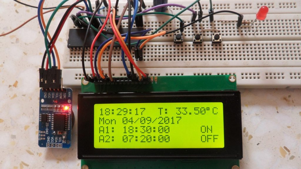
The following picture shows a protoboard circuit of the project:

Proteus simulation of this project should give a result near to the one shown in the video below where 20×4 LCD is used instead of the SSD1306 OLED display: