This is another post that shows how to use ST7789 TFT display with Arduino.
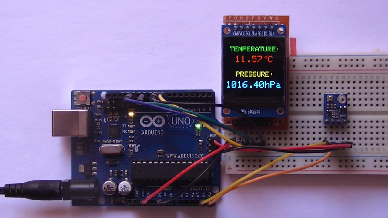
In this project the ST7789 TFT is used to display values of temperature and pressure with the help of BMP280 barometric pressure and temperature sensor.
The ST7789 TFT module contains a display controller with the same name: ST7789. It’s a color display that uses SPI interface protocol and requires 3, 4 or 5 control pins, it’s low cost and easy to use.
The ST7789 TFT is an IPS display, it comes in different sizes (1.3″, 1.54″ …) but all of them should have the same resolution of 240×240 pixel (some may come with 320×240 pixel), this means it has 57600 pixels. This module works with 3.3V only and it doesn’t support 5V (not 5V tolerant).
TFT: Thin-Film Transistor.
SPI: Serial Peripheral Interface.
IPS: In-Plane Switching.
To see how to interface Arduino with ST7789 TFT display, visit this post:
Interfacing Arduino with ST7789 TFT Display – Graphics Test Example
About the BMP280 sensor:
The BMP280 sensor from Bosch Sensortec is a low cost pressure and temperature sensor with good accuracy. Because pressure changes with altitude we can use it as an altimeter with ±1 meter accuracy (pressure accuracy = ±1 hPa). Some parameters of the sensor are listed below:
Pressure range: 300…1100 hPa (equivalent to +9000…-500m above/below sea level)
Pressure resolution: 0.01 hPa ( < 10 cm)
Temperature range: -40…85 °C
Temperature resolution: 0.01 °C
Interface: I2C and SPI
In this project the BMP280 sensor is used in I2C mode.
Hardware Required:
- Arduino uno board
- ST7789 TFT display module (1.3″, 1.54″ …)
- BMP280 sensor module (with built-in 3.3V regulator and level shifter) —-> datasheet
- 4 x 3.3k ohm resistor (+1 if the display module has CS pin)
- 4 x 2.2k ohm resistor (+1 if the display module has CS pin)
- Breadboard
- Jumper wires
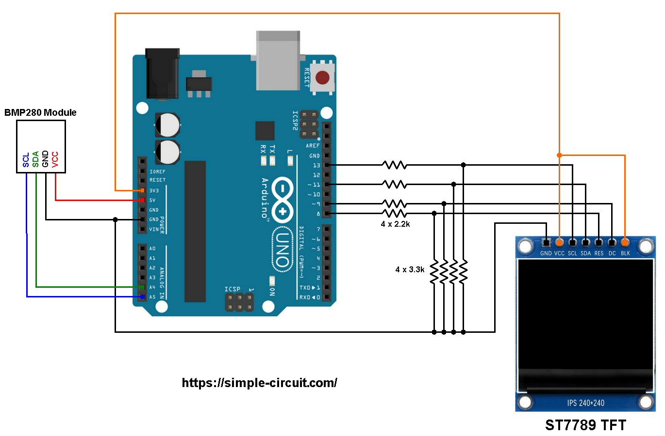
Arduino with BMP280 sensor and ST7789 TFT circuit:
Project circuit schematic diagram is shown below.
Hint:
The BMP280 chip works with maximum voltage of 3.6V (supply voltage range is from 1.71 to 3.6V) which means we’ve to use a 3V3 voltage regulator to supply it from a 5V source.
Also, if we’re working with a 5V system (development board, microcontroller …) like the Arduino UNO board (ATmega328P microcontroller), we’ve to use a voltage level shifter (level converter) which converts the 3.3V (comes from the BMP280 chip) into 5V (goes to the ATmega328P) and vice versa. This level shifter is for the I2C bus lines (clock and data).
The BMP280 module shown in project circuit diagram has a built-in 3.3V regulator and level shifter.
Generally, the BMP280 sensor module has at least 4 pins because it can work in SPI mode or I2C mode. For the I2C mode we need 4 pins: VCC, GND, SDA and SCL where:
VCC is power supply pin, it is connected to Arduino 5V pin,
GND (ground) is connected to Arduino GND pin,
SDA is I2C bus serial data line, connected to Arduino analog pin 4 (A4),
SCL is I2C bus serial clock line, connected to Arduino analog pin 5 (A5).
The ST7789 display module shown in project circuit diagram has 7 pins: (from right to left): GND (ground), VCC, SCL (serial clock), SDA (serial data), RES (reset), DC (or D/C: data/command) and BLK (back light).
Connecting the BLK pin is optional. The back light turns off when the BLK pin connected to the ground (GND).
As mentioned above, the ST7789 TFT display controller works with 3.3V only (power supply and control lines). The display module is supplied with 3.3V (between VCC and GND) which comes from the Arduino board.
All Arduino UNO board output pins are 5V, connecting a 5V pin to the ST7789 TFT display may damage its controller.
To connect the Arduino to the display module, I used voltage divider for each line which means there are 4 voltage dividers. Each voltage divider consists of 2.2k and 3.3k resistors, this drops the 5V into 3V which is sufficient.
If the display module has a CS pin (Chip Select) then it should be connected to Arduino digital pin 10 through another voltage divider.
So, the ST7789 TFT display is connected to the Arduino board as follows (each one through voltage divider):
RST pin is connected to Arduino digital pin 8,
DC pin is connected to Arduino digital pin 9,
SDA pin is connected to Arduino digital pin 11,
SCL pin is connected to Arduino digital pin 13.
Other pins are connected as follows:
VCC pin is connected to Arduino 3V3 pin,
GND pin is connected to Arduino GND pin,
BL (LED) pin is connected to Arduino 3V3 pin (optional).
Arduino with BMP280 sensor and ST7789 TFT code:
The following Arduino code requires 3 libraries from Adafruit Industries:
The first library is a driver for the ST7789 TFT display which can be installed from Arduino IDE library manager (Sketch —> Include Library —> Manage Libraries …, in the search box write “st7789” and install the one from Adafruit).
The second library is Adafruit graphics library which can be installed also from Arduino IDE library manager.
The 3rd library is for the BMP280 sensor, it may be installed using library manager (in the search box write “bmp280” and choose the one from Adafruit).
The 3 libraries can be installed manually, first download them from the following links:
Adafruit ST7789 TFT library —-> direct link
Adafruit graphics library —-> direct link
Adafruit BMP280 Library —-> direct link
You may need to install Adafruit Unified Sensor library if it’s not already installed, download link is below:
Adafruit Unified Sensor library —-> direct link
After the download, go to Arduino IDE —> Sketch —> Include Library —> Add .ZIP Library … and browse for the .zip file (previously downloaded).
The same thing for the other library files.
Hints:
The libraries are included in the main code as follows:
1 2 3 | #include <Adafruit_GFX.h> // Adafruit core graphics library #include <Adafruit_ST7789.h> // Adafruit hardware-specific library for ST7789 #include <Adafruit_BMP280.h> // Adafruit BMP280 sensor library |
The ST7789 TFT module pins (CS, RST and DC) connections are defined as shown below (even the display module has no CS pin but its definition is required by the Adafruit ST7789 library):
1 2 3 4 | // ST7789 TFT module connections #define TFT_CS 10 // define chip select pin #define TFT_DC 9 // define data/command pin #define TFT_RST 8 // define reset pin, or set to -1 and connect to Arduino RESET pin |
The other display pins (SDA and SCL) are connected to Arduino hardware SPI module pins (digital pin 11 and digital pin 13 respectively for MOSI and SCLK).
The Adafruit ST7789 library is initialized with this line:
1 | Adafruit_ST7789 tft = Adafruit_ST7789(TFT_CS, TFT_DC, TFT_RST); |
And the TFT display is initialized using the following command:
1 2 3 | // initialize the ST7789 display (240x240 pixel) // if the display has CS pin try with SPI_MODE0 tft.init(240, 240, SPI_MODE2); |
As any other I2C device, the BMP280 sensor has an I2C slave address which may be 0x76 or 0x77. This address depends on the connection of the SDO pin (used for SPI mode as serial data out or MISO), if the SDO pin is connected (directly or through resistor) to VCC (3.3V) the address will be 0x77, and if it’s connected to GND the address will be 0x76.
The default I2C address of the BMP280 library is defined as 0x77 and my device I2C address is 0x76.
In the code, the definition of the I2C slave address and the initialization of its library are shown below:
1 2 3 4 | // define device I2C address: 0x76 or 0x77 (0x77 is library default address) #define BMP280_I2C_ADDRESS 0x76 // initialize Adafruit BMP280 library Adafruit_BMP280 bmp280; |
The initialization of the BMP280 sensor is done using the function begin() which returns 1 if OK and 0 if error. In the code the initialization with the previously defined address is as shown below:
1 | bmp280.begin(BMP280_I2C_ADDRESS) |
Reading the values of temperature and pressure:
1 2 3 | // read temperature and pressure from the BMP280 sensor float temp = bmp280.readTemperature(); // get temperature float pressure = bmp280.readPressure(); // get pressure |
Note that the BMP280 sensor library returns the value of the pressure in Pa unit and to convert it to hPa we’ve to divide it by 100.
1 bar = 10000 Pa = 100 hPa. ( 1 hPa = 100 Pa = 1 millibar)
Pa: Pascal
hPa: hectoPascal
Temperature and pressure values are displayed on the ST7789 TFT display.
If there is a problem with the BMP280 sensor (for example wrong device address) the screen will display Connection Error
Full Arduino Code:
1 2 3 4 5 6 7 8 9 10 11 12 13 14 15 16 17 18 19 20 21 22 23 24 25 26 27 28 29 30 31 32 33 34 35 36 37 38 39 40 41 42 43 44 45 46 47 48 49 50 51 52 53 54 55 56 57 58 59 60 61 62 63 64 65 66 67 68 69 70 71 72 73 74 75 76 77 78 79 80 81 82 83 84 85 86 87 88 89 90 91 92 93 94 95 96 | /*********************************************************************** * * Arduino with ST7789 TFT display (240x240 pixel) and BMP280 * barometric pressure & temperature sensor.. * This is a free software with NO WARRANTY. * http://simple-circuit.com/ * ***********************************************************************/ #include <Adafruit_GFX.h> // Adafruit core graphics library #include <Adafruit_ST7789.h> // Adafruit hardware-specific library for ST7789 #include <Adafruit_BMP280.h> // Adafruit BMP280 sensor library // ST7789 TFT module connections #define TFT_CS 10 // define chip select pin #define TFT_DC 9 // define data/command pin #define TFT_RST 8 // define reset pin, or set to -1 and connect to Arduino RESET pin // initialize Adafruit ST7789 TFT library with hardware SPI module // MOSI(SDA) ---> Arduino digital pin 11 // SCK (SCL) ---> Arduino digital pin 13 Adafruit_ST7789 tft = Adafruit_ST7789(TFT_CS, TFT_DC, TFT_RST); // define device I2C address: 0x76 or 0x77 (0x77 is library default address) #define BMP280_I2C_ADDRESS 0x76 // initialize Adafruit BMP280 library Adafruit_BMP280 bmp280; void setup(void) { // initialize the ST7789 display (240x240 pixel) // if the display has CS pin try with SPI_MODE0 tft.init(240, 240, SPI_MODE2); // if the screen is flipped, remove this command tft.setRotation(2); // fill the screen with black color tft.fillScreen(ST77XX_BLACK); tft.setTextWrap(false); // turn off text wrap option // initialize the BMP280 sensor if( bmp280.begin(BMP280_I2C_ADDRESS) == 0 ) { // connection error or device address wrong! tft.setTextColor(ST77XX_WHITE, ST77XX_BLACK); // set text color to white and black background tft.setTextSize(4); // text size = 4 tft.setCursor(3, 88); // move cursor to position (3, 88) pixel tft.print("Connection"); tft.setCursor(63, 126); // move cursor to position (63, 126) pixel tft.print("Error"); while(1); // stay here } tft.setTextColor(ST77XX_GREEN, ST77XX_BLACK); // set text color to green and black background tft.setTextSize(3); // text size = 3 tft.setCursor(17, 31); // move cursor to position (17, 31) pixel tft.print("TEMPERATURE:"); tft.setTextColor(ST77XX_YELLOW, ST77XX_BLACK); // set text color to yellow and black background tft.setCursor(44, 140); // move cursor to position (44, 140) pixel tft.print("PRESSURE:"); tft.setTextSize(4); // text size = 4 } // variables char _buffer[11]; // main loop void loop() { delay(1000); // wait a second // read temperature and pressure from BMP280 sensor float temp = bmp280.readTemperature(); // get temperature float pressure = bmp280.readPressure(); // get pressure // print temperature (in °C) if(temp < 0) // if temperature < 0 sprintf( _buffer, "-%02u.%02u", (int)abs(temp), (int)(abs(temp) * 100) % 100 ); else // temperature >= 0 sprintf( _buffer, " %02u.%02u", (int)temp, (int)(temp * 100) % 100 ); tft.setTextColor(ST77XX_RED, ST77XX_BLACK); // set text color to yellow and black background tft.setCursor(15, 71); tft.print(_buffer); tft.drawCircle(171, 77, 4, ST77XX_RED); // print degree symbol ( ° ) tft.drawCircle(171, 77, 5, ST77XX_RED); tft.setCursor(180, 71); tft.print("C"); // 2: print pressure (in hPa) sprintf( _buffer, "%04u.%02uhPa", (int)(pressure/100), (int)((uint32_t)pressure % 100) ); tft.setTextColor(ST77XX_CYAN, ST77XX_BLACK); // set text color to cyan and black background tft.setCursor(0, 181); tft.print(_buffer); } // end of code. |
The following video shows my simple hardware circuit:
Related Project:
Arduino with ST7789 TFT and BME280 Sensor – Weather Station Project


