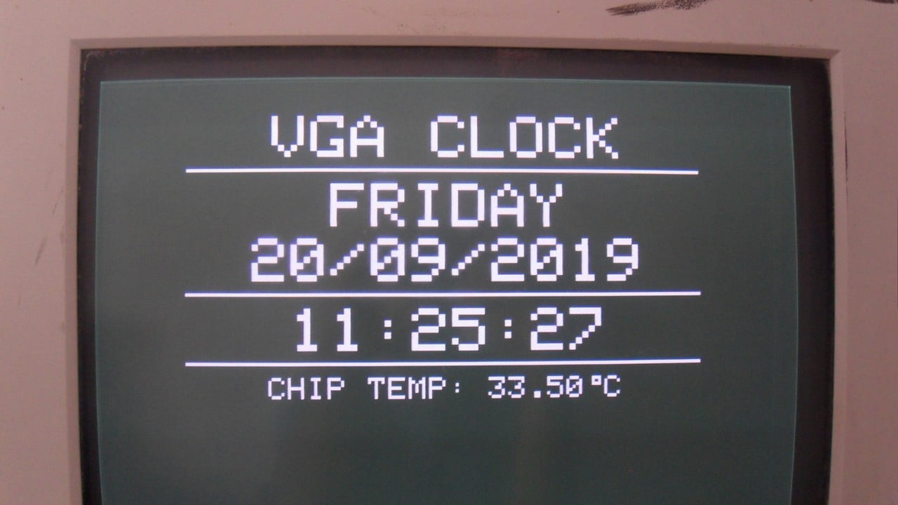
This PIC project shows how to make real time clock & calendar (RTCC) using PIC18F46K22 microcontroller and DS3231 RTCC module. Time & date are displayed on VGA monitor and they may be set with two push buttons connected to the PIC18F46K22 MCU.
As an addition to time and date read/set, the PIC18F46K22 MCU works as a VGA driver by generating the required signals with resolution of 160×96 pixel and 1-bit color (black and white).
This project builds a VGA clock.
CCS C compiler is used in this project.
VGA: Video Graphics Array.
To see how to interface the PIC18F46K22 MCU with VGA monitor, visit this post:
Interfacing PIC18F46K22 MCU with VGA Monitor – Graphics Test Example
The DS3231 RTC has built-in temperature sensor with resolution of 0.25 °C and accuracy of ±3 °C. Chip temperature also will be printed on the VGA monitor.
Hardware required:
- PIC18F46K22 microcontroller
- VGA monitor
- DS3231 board —-> DS3231 datasheet
- 2 x push button
- 2 x 68 ohm resistor
- 220 ohm resistor
- VGA connector
- 3V coin cell battery
- 5V source
- Breadboard
- Jumper wires
VGA Clock with PIC18F46K22 and DS3231 circuit:
The following image shows project circuit diagram.
The PIC18F46K22 microcontroller has 2 hardware I2C modules (MSSP1 and MSSP2 modules).
In this project I2C1 module is used with SDA1 on pin RC4 (#23) and SCL1 on pin RC3 (#18). SDA1 and SCL1 pins of the PIC18F46K22 MCU are respectively connected to SDA and SCL pins of the DS3231 RTC board.
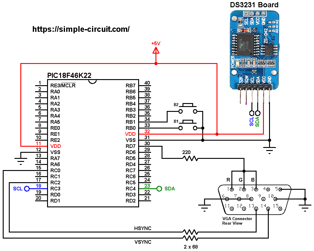
All the grounded terminals are connected together, don’t forget the negative terminal of the 5V source!
HSYNC (horizontal synchronization) pin of the VGA connector (pin #13) is connected to PIC18F46K22 microcontroller pin RC2 (#17) through 68 ohm resistor.
VSYNC (vertical synchronization) pin of the VGA connector (#14) is connected to PIC18F46K22 microcontroller pin RC0 (#15) through 68 ohm resistor.
Color pins (R: red, G: green, B: blue) of the VGA connector (respectively #1, #2 and #3) are connected together in order to get white and black colors, they are connected to PIC18F46K22 microcontroller pin RD7 (#30) through 220 ohm resistor.
Pins 5, 6, 7, 8 and 10 of the VGA connector are connected to ground.
In this project the PIC18F46K22 microcontroller runs with its internal oscillator @ 64 MHz (16 MIPS), MCLR pin is configured as input.
VGA Clock with PIC18F46K22 and DS3231 code:
The C code below is for CCS C compiler, it was tested with version 5.083.
The following CCS C code requires 3 libraries:
The first library is for generating the required VGA signals (VSYNC, HSYNC and video). Its full name (with extension) is VGA.c, download link is below:
VGA Library for CCS C compiler
The 2nd one is graphics library. This library helps us to easily print texts and draw shapes, its full name is GFX_Library.c, download link is the one below:
Graphics library for CCS C compiler:
The third library is a driver for the DS3231 RTC, its full name is: DS3231.c:
DS3231 CCS C driver
After the download of the 3 library files, add all of them to CCS C project folder.
The previous 3 libraries are included in the C code as shown below:
1 2 3 | #include <DS3231.c> // include DS3231 driver source file #include <VGA.c> // include VGA driver source code #include <GFX_Library.c> // include graphics library source code |
The VGA display is used with resolution of 160×96 pixel, the height is set using this line (the width is always fixed to 160 pixel):
1 2 | // use 96 pixel height #define VGAHEIGHT_96 |
Functions used in the code:
int1 debounce (): this function is for button B1 debounce, returns 1 if button is debounced.
void dow_print(): displays day of the week (Monday, Tuesday …) on the screen.
void rtc_print(): displays time, date and day of the week on the screen. This function calls the previous one for displaying day of the week.
void wait(): this function is just a delay of 500 ms except that it can be interrupted by the two push buttons (B1 and B2). In this function Timer0 module is used to count the 500 milliseconds, it is used as 16-bit timer with prescaler = 128 (==> 1 tick every 8 microseconds ==> 62500 x 8 = 500000 us = 500 ms).
int8 edit(char parameter): this function is for setting the real time clock, returns the edited parameter.
Rest of code is described through comments.
Full CCS C code:
1 2 3 4 5 6 7 8 9 10 11 12 13 14 15 16 17 18 19 20 21 22 23 24 25 26 27 28 29 30 31 32 33 34 35 36 37 38 39 40 41 42 43 44 45 46 47 48 49 50 51 52 53 54 55 56 57 58 59 60 61 62 63 64 65 66 67 68 69 70 71 72 73 74 75 76 77 78 79 80 81 82 83 84 85 86 87 88 89 90 91 92 93 94 95 96 97 98 99 100 101 102 103 104 105 106 107 108 109 110 111 112 113 114 115 116 117 118 119 120 121 122 123 124 125 126 127 128 129 130 131 132 133 134 135 136 137 138 139 140 141 142 143 144 145 146 147 148 149 150 151 152 153 154 155 156 157 158 159 160 161 162 163 164 165 166 167 168 169 170 171 172 173 174 175 176 177 178 179 180 181 182 183 184 185 186 187 188 189 190 191 192 193 194 195 196 197 198 199 200 | /************************************************************************** VGA Clock with PIC18F46K22 microcontroller and DS3231 RTC. VGA display resolution: 160x96 pixel. C Code for CCS C compiler. This is a free software with NO WARRANTY. http://simple-circuit.com/ /**************************************************************************/ // use 96 pixel height #define VGAHEIGHT_96 // button definitions #define button1 PIN_B0 // button B1 is connected to RB0 pin #define button2 PIN_B1 // button B2 is connected to RB1 pin #include <18F46K22.h> #fuses NOMCLR, NOLVP, NOBROWNOUT, PUT, NOXINST #use delay(internal = 64MHz) #use fast_io(b) #use fast_io(c) #use fast_io(d) #use I2C(MASTER, I2C1, FAST = 400000, STREAM = DS3231_STREAM) #include <DS3231.c> // include DS3231 driver source file #include <VGA.c> // include VGA driver source code #include <GFX_Library.c> // include graphics library source code // DS3231 library variable declaration RTC_Time *mytime; // a small function for button1 (B1) debounce int1 debounce () { int8 count = 0; for(int8 i = 0; i < 5; i++) { if ( !input(button1) ) count++; delay_ms(5); } if(count > 2) return 1; else return 0; } void dow_print() { int8 dow_matrix[7][10] = {"SUNDAY", "MONDAY", "TUESDAY", "WEDNESDAY", "THURSDAY", "FRIDAY", "SATURDAY"}; static const int8 x_pos[7] = {45, 45, 39, 27, 33, 45, 33}; if( mytime->dow < 1 || mytime->dow > 7) mytime->dow = 1; display_fillRect(27, 23, 106, 14, BLACK); display_setCursor( x_pos[mytime->dow - 1], 23 ); printf( display_print,dow_matrix[mytime->dow - 1] ); } void rtc_print() { // print day of the week static int8 previous_dow = 8; if( previous_dow != mytime->dow ) { previous_dow = mytime->dow; dow_print(); } // print date display_setCursor(21, 41); printf(display_print, "%02u/%02u/20%02u", mytime->day, mytime->month, mytime->year); // print time display_setCursor(33, 64); printf(display_print, "%02u:%02u:%02u", mytime->hours, mytime->minutes, mytime->seconds); // read and print chip temperature signed int16 chip_temp = Get_Temperature(); display_setTextSize(1); // set text size to 1 display_setCursor(86, 87); if (chip_temp < 0) // if temperature is negative printf(display_print, "-%02Lu.%02Lu", abs(chip_temp) / 100, abs(chip_temp) % 100); else printf(display_print, " %02Lu.%02Lu", chip_temp / 100, (chip_temp % 100)); display_setTextSize(2); // set text size to 2 } void wait() { set_timer0(0); // reset Timer0 while( (get_timer0() < 62500L) && input(button1) && input(button2) ) ; } int8 edit(int8 parameter) { static int8 i = 0, y_pos; static const int8 x_pos[5] = {21, 57, 117, 33, 69}; if(i < 3) y_pos = 41; else y_pos = 64; while( debounce() ); // call debounce function (wait for B1 to be released) while(TRUE) { while(!input(button2)) { parameter++; if(i == 0 && parameter > 31) // if day > 31 ==> day = 1 parameter = 1; if(i == 1 && parameter > 12) // if month > 12 ==> month = 1 parameter = 1; if(i == 2 && parameter > 99) // if year > 99 ==> year = 0 parameter = 0; if(i == 3 && parameter > 23) // if hours > 23 ==> hours = 0 parameter = 0; if(i == 4 && parameter > 59) // if minutes > 59 ==> minutes = 0 parameter = 0; display_setCursor(x_pos[i], y_pos); printf(display_print, "%02u", parameter); delay_ms(200); } display_fillRect(x_pos[i], y_pos, 22, 14, BLACK); wait(); display_setCursor(x_pos[i], y_pos); printf(display_print, "%02u", parameter); wait(); if( !input(button1) ) { i = (i + 1) % 5; // increment 'i' for the next parameter return parameter; // return parameter value and exit } } } // main function void main(void) { VGA_begin(); // VGA init display_clear(); // clears the screen and buffer port_b_pullups(0x03); // enable RB0 & RB1 internal pull-ups display_drawLine(0, 18, display_width-1, 18, WHITE); display_drawLine(0, 59, display_width-1, 59, WHITE); display_drawLine(0, 82, display_width-1, 82, WHITE); display_setTextSize(1); // set text size to 1 display_setTextColor(WHITE, BLACK); // set text color to white with black background display_setCursor(26, 87); // move cursor to position (26, 87) display_print("CHIP TEMP: 00.00 C"); // print text display_drawRect(124, 87, 3, 3, WHITE); // print degree symbol ( ° ) display_setTextSize(2); // set text size to 2 display_setCursor(27, 0); display_print("VGA CLOCK"); while(TRUE) { // read current time and date mytime = RTC_Get(); rtc_print(); if( !input(button1) ) // if button B1 is pressed if( debounce() ) // call debounce function (make sure if B1 is pressed) { while( debounce() ); // call debounce function (wait for B1 to be released) setup_timer_0(T0_INTERNAL | T0_DIV_128); // start Timer0 with internal clock & prescaler=128 (1 tick/us) while(TRUE) { while( !input(button2) ) // if button B2 button is pressed { mytime->dow++; if(mytime->dow > 7) mytime->dow = 1; dow_print(); // print week day delay_ms(300); } display_fillRect(27, 23, 106, 14, BLACK); wait(); // call wait() function dow_print(); // print week day wait(); // call wait() function if( !input(button1) ) // if button B1 is pressed break; } mytime->day = edit(mytime->day); // edit day mytime->month = edit(mytime->month); // edit month mytime->year = edit(mytime->year); // edit year mytime->hours = edit(mytime->hours); // edit hours mytime->minutes = edit(mytime->minutes); // edit minutes mytime->seconds = 0; // reset seconds while( debounce() ); // call debounce function (wait for button B1 to be released) setup_timer_0(T0_OFF); // turn off Timer0 // write data to the RTC chip RTC_Set(mytime); } delay_ms(100); // wait 100 milliseconds } } // end of code. |
The following video shows my hardware circuit test: