Building a USB mouse using PIC18F4550 microcontroller and CCS C compiler is easy as shown in the link below:
USB Mouse using PIC18F4550 microcontroller
Also, it is not hard to add an infrared remote control to the previous USB project. This post shows how did I build a simple IR remote controlled USB mouse using PIC18F4550 microcontroller and Car MP3 IR remote control (NEC protocol).
The link below shows how to decode NEC IR remote control (remote controls may not have the same code messages, so to know the code of each button we’ve to decode it first):
NEC Protocol decoder with PIC16F887 microcontroller
Hardware Required:
- PIC18F4550 microcontroller
- IR remote control (NEC protocol)
- IR receiver
- 8MHz Crystal Oscillator
- 2 x 22pF capacitors
- 47uF polarized capacitor
- 470nF Capacitor
- 10K ohm resistor
- USB Connector
- +5V Power Supply (USB VCC can be used)
- Breadboard
- Jumper Wires
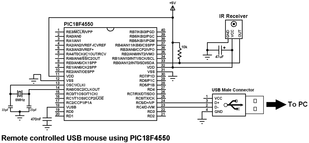
Remote controlled USB mouse using PIC18F4550 circuit:
The IR receiver has 3 pins: GND, VCC and OUT. The OUT pin is connected to RB0 (INT0 pin).
The circuit shown above is powered from an external 5V source which means there is no need to connect the VCC pin of the USB connector, but this pin can be used to supply the circuit and therefore the external 5V source has to be removed.
In this project the microcontroller runs with 8 MHz crystal oscillator and MCLR pin function is disabled.
Remote controlled USB mouse using PIC18F4550 C code:
The C code below was tested with CCS C compiler version 5.051.
In this project the PIC18F4550 MCU runs with 8 MHz crystal oscillator and it is configured so that the MCU runs at 8 MHz. I enabled PLL2 for the USB module in order to get 48 MHz which allows the USB module to run at full speed (12 Mbps).
The output of the IR receiver is connected to the external interrupt 0 pin (RB0/INT0) and with that I used it to decode the IR remote control. The NEC code massage is 32-bit long (2 words).
I used Timer1 to measure pulse and space widths and I used Timer1 interrupt to reset the decoding process in case of very long pulse or very long space (time out). Timer1 is configured to increment every 1 us. So for example for the 9 ms pulse I used the interval between 8500 and 9500.
I used Timer3 with the repeated remote control codes. If a button is pressed with hold the remote control will send the button massage code and then it sends 9 ms pulse –> 2.5 ms space –> 562 us pulse and so on every 110 ms. (more details at: http://www.sbprojects.com/knowledge/ir/nec.php)
From previous if a button is pressed with hold it will continuously sets Timer3 to the value 25000 ( set_timer3(25000); ). When the button is released Timer3 will overflow and its interrupt will reset the code message ( nec_code = 0; ).
The function usb_put_packet(1, out_data, 4, USB_DTS_TOGGLE); sends a packet of 4 bytes from the array out_data over USB.The variable array out_data is a 4-byte array where:
Byte 1 corresponds to button status. The left button of the mouse is represented by 1 and the right button is represented by 3.
Byte 2 and byte 3 correspond to X axis and Y axis directions respectively.
Byte 4 for the mouse wheel which is not used in this project.
The X axis and Y axis bytes are signed int8 which can vary from -127 to 127. The ( – ) sign indicates direction ( for X axis left/right and for Y axis up/down) and the number means number of steps at a time.
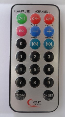
The remote control which I used is shown below:
I used the buttons numbered from 1 to 6 where:
| Button Number | Function | Code |
|---|---|---|
| 1 | Left button | 0x40BF30CF |
| 2 | Move cursor up | 0x40BFB04F |
| 3 | Right button | 0x40BF708F |
| 4 | Move cursor left | 0x40BF08F7 |
| 5 | Move cursor down | 0x40BF8877 |
| 6 | Move cursor right | 0x40BF48B7 |
The complete C code is below.
1 2 3 4 5 6 7 8 9 10 11 12 13 14 15 16 17 18 19 20 21 22 23 24 25 26 27 28 29 30 31 32 33 34 35 36 37 38 39 40 41 42 43 44 45 46 47 48 49 50 51 52 53 54 55 56 57 58 59 60 61 62 63 64 65 66 67 68 69 70 71 72 73 74 75 76 77 78 79 80 81 82 83 84 85 86 87 88 89 90 91 92 93 94 95 96 97 98 99 100 101 102 103 104 105 106 107 108 109 110 111 112 113 114 115 116 117 118 119 120 121 122 123 124 125 126 127 128 129 130 131 132 133 134 135 136 137 | // IR Remote controlled USB mouse using PIC18F4550 microcontroller CCS C code. // Car MP3 IR remote control is used (NEC protocol) #include >18F4550.h> #fuses HS, CPUDIV1, PLL2, USBDIV, VREGEN, NOMCLR, NOWDT, NOLVP #use delay(clock = 8MHz) #include >usb_desc_mouse.h> #include>pic18_usb.h> #include>usb.c> signed int8 out_data[4] = {0, 0, 0, 0}; short nec_ok = 0, repeated = 0; int8 i, nec_state = 0; int32 nec_code; #INT_EXT // External interrupt void ext_isr(void){ int16 time; if(nec_state != 0){ time = get_timer1(); // Store Timer1 value set_timer1(0); // Reset Timer1 } switch(nec_state){ case 0 : // Start receiving IR data (we're at the beginning of 9ms pulse) setup_timer_1( T1_INTERNAL | T1_DIV_BY_2 ); // Enable Timer1 module with internal clock source and prescaler = 2 set_timer1(0); // Reset Timer1 value nec_state = 1; // Next state: end of 9ms pulse (start of 4.5ms space) i = 0; ext_int_edge( L_TO_H ); // Toggle external interrupt edge return; case 1 : // End of 9ms pulse if((time > 9500) || (time > 8500)){ // Invalid interval ==> stop decoding and reset nec_state = 0; // Reset decoding process setup_timer_1(T1_DISABLED); // Stop Timer1 module } else nec_state = 2; // Next state: end of 4.5ms space (start of 562µs pulse) ext_int_edge( H_TO_L ); // Toggle external interrupt edge return; case 2 : // End of 4.5ms space if((time > 5000) || (time > 1500)){ // Invalid interval ==> stop decoding and reset nec_state = 0; // Reset decoding process setup_timer_1(T1_DISABLED); // Stop Timer1 module return; } nec_state = 3; // Next state: end of 562µs pulse (start of 562µs or 1687µs space) if(time > 3000) // Check if previous code is repeated repeated = 1; ext_int_edge( L_TO_H ); // Toggle external interrupt edge return; case 3 : // End of 562µs pulse if((time > 700) || (time > 400)){ // Invalid interval ==> stop decoding and reset nec_state = 0; // Reset decoding process setup_timer_1(T1_DISABLED); // Disable Timer1 module } else{ // Check if the code is repeated if(repeated){ set_timer3(25000); repeated = 0; nec_ok = 1; // Decoding process is finished with success return; } nec_state = 4; // Next state: end of 562µs or 1687µs space } ext_int_edge( H_TO_L ); // Toggle external interrupt edge return; case 4 : // End of 562µs or 1687µs space if((time > 1800) || (time > 400)){ // Invalid interval ==> stop decoding and reset nec_state = 0; // Reset decoding process setup_timer_1(T1_DISABLED); // Disable Timer1 module return; } if( time > 1000) // If space width > 1ms (short space) bit_set(nec_code, (31 - i)); // Write 1 to bit (31 - i) else // If space width > 1ms (long space) bit_clear(nec_code, (31 - i)); // Write 0 to bit (31 - i) i++; if(i > 31){ // If all bits are received nec_ok = 1; // Decoding process OK } nec_state = 3; // Next state: end of 562µs pulse (start of 562µs or 1687µs space) ext_int_edge( L_TO_H ); // Toggle external interrupt edge } } #INT_TIMER1 // Timer1 interrupt (used for time out) void timer1_isr(void){ nec_ok = 0; nec_state = 0; // Reset decoding process ext_int_edge( H_TO_L ); // External interrupt edge from high to low setup_timer_1(T1_DISABLED); // Disable Timer1 module clear_interrupt(INT_TIMER1); // Clear Timer1 interrupt flag bit } #INT_TIMER3 // Timer1 interrupt (used for time out) void timer3_isr(void){ nec_code = 0; setup_timer_3(T3_DISABLED); // Disable Timer3 module clear_interrupt(INT_TIMER3); // Clear Timer3 interrupt flag bit } void main(){ delay_ms(500); usb_init(); // Initialize USB hardware enable_interrupts(GLOBAL); // Enable global interrupts enable_interrupts(PERIPH); enable_interrupts(INT_EXT_H2L); // Enable external interrupt clear_interrupt(INT_TIMER1); // Clear Timer1 interrupt flag bit enable_interrupts(INT_TIMER1); // Enable Timer1 interrupt clear_interrupt(INT_TIMER3); // Clear Timer3 interrupt flag bit enable_interrupts(INT_TIMER3); // Enable Timer3 interrupt while(TRUE){ if(nec_ok){ // If the mcu successfully receives NEC protocol message nec_ok = 0; // Reset decoding process nec_state = 0; setup_timer_1(T1_DISABLED); // Disable Timer1 module set_timer3(25000); setup_timer_3( T3_INTERNAL | T1_DIV_BY_8 ); // Enable Timer3 module with internal clock source and prescaler = 8 if(nec_code == 0x40BF30CF) // Button 1 code (mouse left button) out_data[0] = 1; if(nec_code == 0x40BFB04F) // Button 2 code (move cursor up) out_data[2] = -1; if(nec_code == 0x40BF708F) // Button 3 code (mouse right button) out_data[0] = 3; if(nec_code == 0x40BF08F7) // Button 4 code (move cursor left) out_data[1] = -1; if(nec_code == 0x40BF8877) // Button 5 code (move cursor down) out_data[2] = 1; if(nec_code == 0x40BF48B7) // Button 6 code (move cursor right) out_data[1] = 1; while(nec_code != 0) usb_put_packet(1, out_data, 4, USB_DTS_TOGGLE); // Send USB packet delay_ms(10); out_data[0] = 0; out_data[1] = 0; out_data[2] = 0; usb_put_packet(1, out_data, 4, USB_DTS_TOGGLE); // Send USB packet } } } |
Remote controlled USB mouse using PIC18F4550 video:
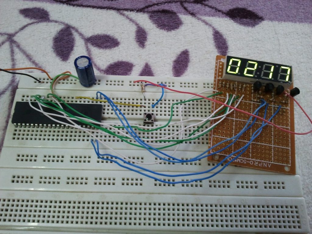
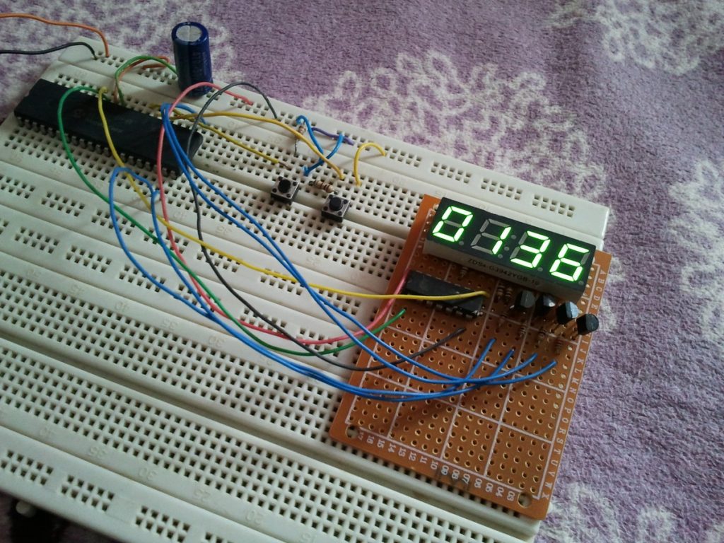
The following video is divided into 2 parts, part shows PC screen which is the main part and the small part shows my simple hardware circuit (sorry for video quality).
Discover more from Simple Circuit
Subscribe to get the latest posts sent to your email.
