PIC16F84A External hardware interrupt example
The microcontroller PIC16F84A has a unique external interrupt at RB0 pin (hardware interrupt). When an interrupt occurred, the microcontroller immediately executes the code attached with the interrupt, after finishing the interrupt code the microcontroller returns to the main code.
This topic shows how to use PIC16F84A microcontroller external hardware interrupt. CCS C compiler is used in this example.
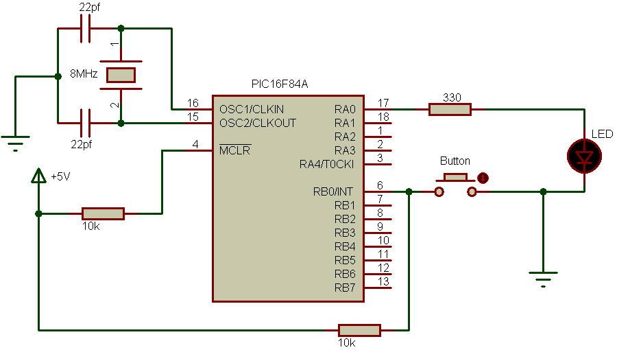
PIC16F84A external interrupt example circuit:

In the circuit schematic above we have just a button and an LED , the button is connected to the external interrupt RB0/INT pin and the LED is connected to RA0 pin. When the button is pressed, an interrupt will occur and the LED will toggle its state (ON or OFF).
The PIC16F84A microcontroller is powered with voltage of 5 Volts between VDD pin (#14) and VSS pin (#5).
Hardware Required:
- PIC16F84A microcontroller —> datasheet
- 8MHz crystal oscillator
- 2 x 22pF ceramic capacitor
- LED
- Push button
- 10k ohm resistor
- 330 ohm resistor
- Bread board and jumper wires
- PIC microcontroller programmer (PICkit 2, PICkit 3…)
PIC16F84A external interrupt example C code:
The C code below is for CCS C compiler, it was tested with version 5.051.
1 2 3 4 5 6 7 8 9 10 11 12 13 14 15 16 17 18 19 20 21 22 23 | // PIC16F84A external interrupt example // https://simple-circuit.com/ #include <16F84A.h> #fuses HS,NOWDT,PUT,NOPROTECT #use delay(crystal=8000000) #INT_EXT void ext_isr(void) { output_toggle(PIN_A0); } void main() { output_low(PIN_A0); ext_int_edge(H_TO_L); // Interrupt on falling edge of RB0/INT pin clear_interrupt(INT_EXT); // Clear RB0/INT external interrupt flag bit enable_interrupts(INT_EXT); // Enable RB0/INT external interrupt enable_interrupts(GLOBAL); // Enable all unmasked interrupt while(TRUE) ; // Endless loop } |
PIC16F84A external interrupt example video:
The following video has some details about the circuit and the CCS C code.
Discover more from Simple Circuit
Subscribe to get the latest posts sent to your email.


