(Some knowledge about RC-5 protocol is required)
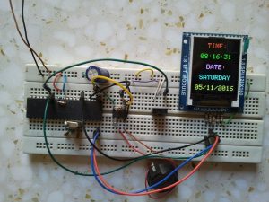
This project shows how to build a remote controlled real time clock with TFT display using PIC18F4550 microcontroller.
In this project DS1307 RTC is used as a real time clock chip and the remote control is an IR (infrared) remote control which uses RC-5 communication protocol, this remote control is used to set time and date. The device used t display time and calendar is 1.8″ ST7735R (ST7735S) SPI TFT display.
To display the ST7735 TFT display with PIC18F4550 microcontroller we need a driver, this driver and some other details about this display can be fount at the following url:
ST7735 SPI TFT Display Driver for CCS PIC C compiler
And the post at the following link shows how to interface this display with PIC18F4550 microcontroller:
Interfacing PIC18F4550 with 1.8″ TFT display
Or simply you can download the ST7735 TFT driver from the following link:
ST7735 SPI TFT Display Driver
The method used to decode RC-5 signals is described in the following topic:
RC5 IR Remote Control Decoder with PIC12F1822 Microcontroller
The decoding process follows the state machine show below:
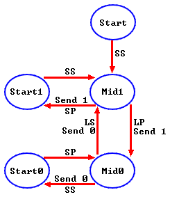
Where:
SP : Short Pulse (About 889µs)
LP : Long Pulse (About 1778µs)
SS: Short Space (About 889µs)
LS : Long Space (About 1778µs)
Basically there are 4 states: Mid1, Mid0, Start1 and Start0.
Components List:
- PIC18F4550 Microcontroller
- ST7735R (ST7735S) 1.8″ SPI TFT Display
- DS1307 RTC Chip
- RC-5 IR Remote Control
- IR Receiver
- 8MHz Crystal Oscillator
- 32.768KHz Crystal Oscillator
- 2 x 22pF Ceramic Capacitors
- 47uF Capacitor
- 3 x 10K Resistor
- 5 x 1K Resistors
- 3V Lithium Coin Cell Battery
- +5V Power Supply Source
- Breadboard
- Jumper Wires
For the DS1307 RTC chip there are many topics in this blog talking about it and how to interface it with different types of PIC microcontrollers for example the topic at the url below:
Real time clock with PIC18F4550 and DS1307 RTC
Real time clock with remote control and ST7735 TFT display circuit:
The following image shows our project circuit schematic where the microcontroller runs with 8MHz external crystal oscillator.

Real time clock with remote control and ST7735 TFT display CCS C code:
In this project the microcontroller runs with 8MHz external crystal oscillator and to make it runs at full speed which is 48MHz we have to use the following fuses:
#fuses NOMCLR HSPLL PLL2 CPUDIV1
Where: PLL2 enables the PLL and divide it by 2
and if for example the crystal oscillator frequency is 12MHz so we have to change PLL2 to PLL3 and so on.
CPUDIV1: No system clock postscaler
PIC18F4550 Microcontroller has only 1 MSSP module which can be configured to work as SPI module or I2C module. In this project we need SPI protocol for the TFT display and I2C for DS1307. Since the TFT display needs a high speed SPI interface, I used PIC18F4550 hardware SPI module to communicate with the TFT display and I implemented a software I2C protocol for DS1307, the following line is used to create a simple software I2C:
#use I2C(master, SDA = PIN_D3, SCL = PIN_D2)
So DS1307 SDA pin is mapped at RD3 and SCL at RD2.
The remote control used in this project is shown below with button codes. This IR remote control is just a TV remote control which use RC5 communication protocol:
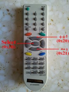
Only 3 buttons are used and the rest have no effect on the circuit.
The button codes displayed in the picture above are the address and command codes combined together. The RC-5 code message is 14 bit long, 2 start bits, a toggle bit, 5 bits as address and 6 bits as command. For example select button which has an address of 0 and command of 0x3B which gives a 16-bit number of 0x3B (toggle bit is neglected).
The toggle bit toggles between 0 and 1. Every time a button is pressed the toggle bit changes. If a button is pressed and kept pressing the toggle bit changes only at the first time and the remote control keep sending the same code of the pressed button with the same toggle bit.
From that I used the toggle bit to check if the select button is pressed again or kept pressing in order to avoid jumping from parameter to another and if you want to go from paramter to another you have to repress the select button.
For the other two buttons (up & down) the toggle bit is not used in order to speed up the setting of the parameters.
The output of the IR receiver is connected to RB2 pin which is external interrupt 2 pin. When the receiver receives an IR signal its output falls (goes form 5V to 0) which makes the microcontroller interrupts. When the mcu interrupts it jumps to interrupt routine ( void ext2_isr(void) ) and starts decoding the IR signal. Timer1 is used to measure pulses and spaces comes from the remote control. The microcontroller decodes the signal according to the state machine above. The interrupt is stopped during DS1307 reading or writing and also during sending data to TFT display.
The following code is tested with CCS PIC C compiler versions 4.068 and 5.051.
1 2 3 4 5 6 7 8 9 10 11 12 13 14 15 16 17 18 19 20 21 22 23 24 25 26 27 28 29 30 31 32 33 34 35 36 37 38 39 40 41 42 43 44 45 46 47 48 49 50 51 52 53 54 55 56 57 58 59 60 61 62 63 64 65 66 67 68 69 70 71 72 73 74 75 76 77 78 79 80 81 82 83 84 85 86 87 88 89 90 91 92 93 94 95 96 97 98 99 100 101 102 103 104 105 106 107 108 109 110 111 112 113 114 115 116 117 118 119 120 121 122 123 124 125 126 127 128 129 130 131 132 133 134 135 136 137 138 139 140 141 142 143 144 145 146 147 148 149 150 151 152 153 154 155 156 157 158 159 160 161 162 163 164 165 166 167 168 169 170 171 172 173 174 175 176 177 178 179 180 181 182 183 184 185 186 187 188 189 190 191 192 193 194 195 196 197 198 199 200 201 202 203 204 205 206 207 208 209 210 211 212 213 214 215 216 217 218 219 220 221 222 223 224 225 226 227 228 229 230 231 232 233 234 235 236 237 238 239 240 241 242 243 244 245 246 247 248 249 250 251 252 253 254 255 256 257 258 259 260 261 262 263 264 265 266 267 268 269 270 271 272 273 274 275 276 277 278 279 280 281 282 283 284 285 286 287 288 289 290 291 292 293 294 295 296 297 298 299 300 301 302 303 304 305 306 307 308 309 310 311 312 313 | /* Real time clock with remote control using PIC18F4550 CCS C code 1.8" ST7735R with balck tap (ST7735S) SPI TFT display is used to diplay time and date DS1307 RTC is used as real time clock chip DS1307 Uses I2C protocol Remote control: TV RC5 IR remote control ST7735 TFT display driver for CCS PIC C compiler is required */ // TFT module connections #define TFT_CS PIN_D1 #define TFT_DC PIN_D0 #define TFT_SPI_HARDWARE // End TFT module connections #include <18F4550.h> #fuses NOMCLR HSPLL PLL2 CPUDIV1 #use delay(clock = 48000000) #include <ST7735_TFT.c> #use fast_io(B) #define IR_Sensor PIN_B2 #use I2C(master, SDA = PIN_D3, SCL = PIN_D2) int1 toggle0, toggle; char *text = "TIME:"; char time[] = " : : " ; char calendar[] = " / /20 "; unsigned int8 second, second10, minute, minute10, hour, hour10, date, date10, month, month10, year, year10, day0, day, i, j ; unsigned int16 ir_code, count; int8 test_pulse(){ count = 0; SET_TIMER1(0); while(!input(IR_Sensor) && (count < 3000)) count = GET_TIMER1(); if((count > 2999) || (count < 1000)) return 0; if(count > 1800) return 1; else return 2; } int8 test_space(){ count = 0; SET_TIMER1(0); while(input(IR_Sensor) && (count < 3000)) count = GET_TIMER1(); if((count > 2999) || (count < 1000)) return 0; if(count > 1800) return 1; else return 2; } // Follow the RC5 state machine to understand short remote_read(){ int8 m = 0, check; mid1: check = test_pulse(); if(check == 0) return FALSE; bit_set(ir_code, 13 - m); m++; if(m > 13) return TRUE; if(check == 1) goto mid0; else goto start1; mid0: check = test_space(); if((check == 0) && (m != 13)) return FALSE; bit_clear(ir_code, 13 - m); m++; if(m > 13) return TRUE; if(check == 1) goto mid1; else goto start0; start1: check = test_space(); if(check != 2) return FALSE; goto mid1; start0: check = test_pulse(); if(check != 2) return FALSE; goto mid0; } void display_day(){ switch(day){ case 1: strcpy (text, "SUNDAY"); drawtext(28, 105, text, ST7735_CYAN, ST7735_BLACK, 2); break; case 2: strcpy (text, "MONDAY"); drawtext(28, 105, text, ST7735_CYAN, ST7735_BLACK, 2); break; case 3: strcpy (text, "TUESDAY"); drawtext(22, 105, text, ST7735_CYAN, ST7735_BLACK, 2); break; case 4: strcpy (text, "WEDNESDAY"); drawtext(10, 105, text, ST7735_CYAN, ST7735_BLACK, 2); break; case 5: strcpy (text, "THURSDAY"); drawtext(16, 105, text, ST7735_CYAN, ST7735_BLACK, 2); break; case 6: strcpy (text, "FRIDAY"); drawtext(28, 105, text, ST7735_CYAN, ST7735_BLACK, 2); break; case 7: strcpy (text, "SATURDAY"); drawtext(16, 105, text, ST7735_CYAN, ST7735_BLACK, 2); break; } } void ds1307_display(){ strcpy (time, " : : "); strcpy (calendar, " / /20 "); second10 = (second & 0x70) >> 4; second = second & 0x0F; minute10 = (minute & 0x70) >> 4; minute = minute & 0x0F; hour10 = (hour & 0x30) >> 4; hour = hour & 0x0F; date10 = (date & 0x30) >> 4; date = date & 0x0F; month10 = (month & 0x10) >> 4; month = month & 0x0F; year10 = (year & 0xF0) >> 4; year = year & 0x0F; time[7] = second + 48; time[6] = second10 + 48; time[4] = minute + 48; time[3] = minute10 + 48; time[1] = hour + 48; time[0] = hour10 + 48; calendar[9] = year + 48; calendar[8] = year10 + 48; calendar[4] = month + 48; calendar[3] = month10 + 48; calendar[1] = date + 48; calendar[0] = date10 + 48; drawtext(16, 41, time, ST7735_GREEN, ST7735_BLACK, 2); drawtext(4, 137, calendar, ST7735_YELLOW, ST7735_BLACK, 2); if(day0 != day){ day0 = day; fillRect(8, 105, 112, 15, ST7735_BLACK); } display_day(); } void ds1307_write(unsigned int8 address, data_){ i2c_start(); // Start I2C i2c_write(0xD0); // DS1307 address i2c_write(address); // Send register address i2c_write(data_); // Write data to the selected register i2c_stop(); // Stop I2C } void ds1307_read(){ i2c_start(); // Start I2C protocol i2c_write(0xD0); // DS1307 address i2c_write(0); // Send register address i2c_start(); // Restart I2C i2c_write(0xD1); // Initialize data read second =i2c_read(1); // Read seconds from register 0 minute =i2c_read(1); // Read minuts from register 1 hour = i2c_read(1); // Read hour from register 2 day = i2c_read(1); // Read day from register 3 date = i2c_read(1); // Read date from register 4 month = i2c_read(1); // Read month from register 5 year = i2c_read(0); // Read year from register 6 i2c_stop(); // Stop I2C protocol } int8 edit(int8 parameter, unsigned int8 xx, unsigned int8 yy, unsigned int16 color){ ir_code = 0; while(TRUE){ if(ir_code == 0x20){ ir_code = 0; parameter++; if(i == 1 && parameter > 23) parameter = 0; if(i == 2 && parameter > 59) parameter = 0; if(i == 3 && parameter > 31) parameter = 1; if(i == 4 && parameter > 12) parameter = 1; if(i == 5 && parameter > 99) parameter = 0; } if(ir_code == 0x21){ ir_code = 0; if(i == 1 && parameter < 1) parameter = 24; if(i == 2 && parameter < 1) parameter = 60; if(i == 3 && parameter < 2) parameter = 32; if(i == 4 && parameter < 2) parameter = 13; if(i == 5 && parameter < 1) parameter = 100; parameter--; } sprintf(text,"%02u", parameter); drawtext(xx, yy, text, color, ST7735_BLACK, 2); j = 0; while((ir_code != 0x20) && (ir_code != 0x21) && ((ir_code != 0x3B) || (toggle0 == toggle)) && (j < 25)){ j++; delay_ms(10); } strcpy (text, " "); drawtext(xx, yy, text, color, ST7735_BLACK, 2); j = 0; while((ir_code != 0x20) && (ir_code != 0x21) && ((ir_code != 0x3B) || (toggle0 == toggle)) && (j < 25)){ j++; delay_ms(10); } if((ir_code == 0x3B) && (toggle0 != toggle)){ toggle0 = toggle; sprintf(text,"%02u", parameter); drawtext(xx, yy, text, color, ST7735_BLACK, 2); return parameter; } } } #INT_EXT2 // External interrupt (INT2) ISR void ext2_isr(void){ if(remote_read()){ toggle = bit_test(ir_code, 11); ir_code &= 0x07FF; } clear_interrupt(INT_EXT2); } void main(){ setup_adc_ports(NO_ANALOGS); // Configure AN pins as digital enable_interrupts(GLOBAL); // Enable global interrupts ext_int_edge(2, H_TO_L); clear_interrupt(INT_EXT2); // Clear RA IOC flag bit SETUP_TIMER_1(T1_INTERNAL | T1_DIV_BY_8); TFT_BlackTab_Initialize(); fillScreen(ST7735_BLACK); drawtext(36, 9, text, ST7735_RED, ST7735_BLACK, 2); strcpy (text, "DATE:"); drawtext(36, 73, text, ST7735_MAGENTA, ST7735_BLACK, 2); while(TRUE){ if((ir_code == 0x3B) && (toggle0 != toggle)){ toggle0 = toggle; // Convert BCD to decimal minute = minute + minute10 * 10; hour = hour + hour10 * 10; date = date + date10 * 10; month = month + month10 * 10; year = year + year10 * 10; // End conversion i = 1; hour = edit(hour, 16, 41, ST7735_GREEN); i = 2; minute = edit(minute, 52, 41, ST7735_GREEN); ir_code = 0; while(TRUE){ if(ir_code == 0x20){ ir_code = 0; day++; if(day > 7) day = 1; } if(ir_code == 0x21){ ir_code = 0; if(day < 2) day = 8; day--; } display_day(); j = 0; while((ir_code != 0x20) && (ir_code != 0x21) && ((ir_code != 0x3B) || (toggle0 == toggle)) && (j < 25)){ j++; delay_ms(10); } fillRect(4, 105, 120, 14, ST7735_BLACK); j = 0; while((ir_code != 0x20) && (ir_code != 0x21) && ((ir_code != 0x3B) || (toggle0 == toggle)) && (j < 25)){ j++; delay_ms(10); } if((ir_code == 0x3B) && (toggle0 != toggle)){ toggle0 = toggle; display_day(); break; } } i = 3; date = edit(date, 4, 137, ST7735_YELLOW); i = 4; month = edit(month, 40, 137, ST7735_YELLOW); i = 5; year = edit(year, 100, 137, ST7735_YELLOW); ir_code = 0; // Convert decimal to BCD minute = ((minute/10) << 4) + (minute % 10); hour = ((hour/10) << 4) + (hour % 10); date = ((date/10) << 4) + (date % 10); month = ((month/10) << 4) + (month % 10); year = ((year/10) << 4) + (year % 10); // End conversion // Save all parametrs in DS1307 chip disable_interrupts(INT_EXT2); // Disable INT2 ds1307_write(1, minute); ds1307_write(2, hour); ds1307_write(3, day); ds1307_write(4, date); ds1307_write(5, month); ds1307_write(6, year); ds1307_write(0, 0); enable_interrupts(INT_EXT2); // Enable INT2 // End saving } disable_interrupts(INT_EXT2); // Disable INT2 ds1307_read(); // Read data from DS1307 RTCC ds1307_display(); // Diaplay time and calendar enable_interrupts(INT_EXT2); // Enable INT2 delay_ms(100); } } |
Real time clock with remote control and ST7735 TFT display video:
Project video ….
Discover more from Simple Circuit
Subscribe to get the latest posts sent to your email.


