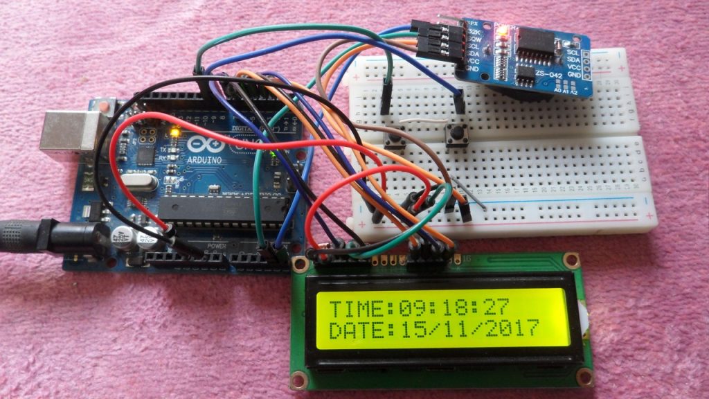
This topic shows how to interface Arduino UNO board with DHT11 digital humidity and temperature sensor where the measure humidity and temperature are displayed on 1602 LCD screen.
DHT11 Sensor technical specifications:
- Humidity Range: 20-90% RH
- Humidity Accuracy: ±5% RH
- Temperature Range: 0-50 °C
- Temperature Accuracy: ±2 °C
- Operating Voltage: 3V to 5.5V
- Resolution = 1
Hardware Required:
- Arduino board
- DHT11 (RHT01) sensor
- 1602 LCD screen
- 4.7K ohm resistor
- 10K ohm variable resistor
- 330 ohm resistor
- Breadboard
- Jumper wires
Arduino + DHT11 + LCD connection circuit:
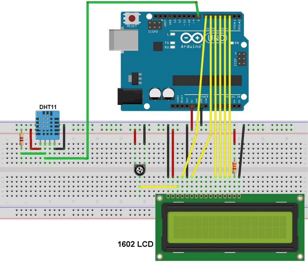
Our interfacing circuit diagram is shown below.
As show in the circuit schematic the DHT11 sensor has 4 pins: VCC (+5V), Data, NC(not connected pin) and GND (from left to right). A pull-up resistor should be added to the data pin with a value between 4.7K and 10K.
The 10K variable resistor is used to control the contrast of the LCD screen and the 330 ohm resistor supplies the LCD backlight LED.
Arduino code:
In this interfacing I used DHT sensors library (DHT11, DHT21 and DHT22) from Adafruit. This library initiates the DHT11 sensor and reads the values of the humidity and temperature.
Since the DHT11 sensor resolution is 1, the values of the humidity and temperature are stored in two variables with type byte (8-bit unsigned), I named them RH (for the humidity) and Temp (for the temperature).
The values of the humidity and temperature needs to be displayed on the LCD after the reading, and for that I used two character arrays named: temperature (char temperature[] = “Temp = 00.0 C “;) and humidity (char humidity[] = “RH = 00.0 % “;). Humidity and temperature values are copied to the previous arrays before displaying it. For example the temperature value is copied to the array temperature as follows:
temperature[7] = Temp / 10 + 48;
This line means the 7th character of the array is equal to the tens of temperature value
temperature[8] = Temp % 10 + 48; (Temp%10 equals to the remainder of Temp/10)
and this line means the 8th character of the array is equal to the ones of temperature value. For example if the temperature value is 42 ==> 42 / 10 = 4 and 42 % 10 = 2.
The number 48 is used to convert decimal numbers to AscII because the LCD works with AscII format.
The line temperature[11] = 223; means adding the degree symbol (°).
1 2 3 4 5 6 7 8 9 10 11 12 13 14 15 16 17 18 19 20 21 22 23 24 25 26 27 28 29 30 31 32 33 34 35 36 37 38 39 40 41 42 43 44 45 46 47 48 | // Interfacing Arduino with DHT11 humidity and temperature sensor // include LCD library code #include <LiquidCrystal.h> // include DHT library code #include "DHT.h" #define DHTPIN 8 // DHT11 data pin is connected to Arduino pin 8 // LCD module connections (RS, E, D4, D5, D6, D7) LiquidCrystal lcd(7, 6, 5, 4, 3, 2); #define DHTTYPE DHT11 // DHT11 sensor is used DHT dht(DHTPIN, DHTTYPE); // Initialize DHT library char temperature[] = "Temp = 00.0 C "; char humidity[] = "RH = 00.0 % "; void setup() { // set up the LCD's number of columns and rows lcd.begin(16, 2); dht.begin(); } void loop() { delay(1000); // wait 1s between readings // Read humidity byte RH = dht.readHumidity(); //Read temperature in degree Celsius byte Temp = dht.readTemperature(); // Check if any reads failed and exit early (to try again) if (isnan(RH) || isnan(Temp)) { lcd.clear(); lcd.setCursor(5, 0); lcd.print("Error"); return; } temperature[7] = Temp / 10 + 48; temperature[8] = Temp % 10 + 48; temperature[11] = 223; humidity[7] = RH / 10 + 48; humidity[8] = RH % 10 + 48; lcd.setCursor(0, 0); lcd.print(temperature); lcd.setCursor(0, 1); lcd.print(humidity); } |
Arduino + DHT11 simulation video:
The video below shows simulation of the example using Proteus.
Downloads:
Adafruit library for DHT series (after extracting put the folder named DHT in the library folder of Arduino):
Download
To be able to simulate this example, Proteus needs the Arduino library which can be downloaded from the link below. After extracting the files (ARDUINO.IDX and ARDUINO.LIB) put it in the Library folder (ex: C:\Program Files\Labcenter Electronics\Proteus 8 Professional\LIBRARY):
Download
Arduino + DHT11 + LCD Proteus simulation file download:
Download
Discover more from Simple Circuit
Subscribe to get the latest posts sent to your email.


DHT11 sensor is much more accurate than LM335 from your previous project
Wow, what an informative and detailed guide on using the DHT11 sensor with an LCD in Proteus! This step-by-step tutorial has truly shed light on how to effectively integrate these components for temperature and humidity monitoring in Arduino projects.
Hello, can anyone give me the assembly code for this circuit, it’s urgent please ?
xit status 1
DHT.h: No such file or directory
I am getting this error while compiling the code how can I resolve this ? plz someone guide me
what board to use?
how to represent the decimals?
where in the code I put that? I just start to play with arduino.
how to change to fahranheit
T(°F) = T(°C) × 9/5 + 32
or
T(°F) = T(°C) × 1.8 + 32
can you post sample for fahranheit? I can not figure it.
OK.
Replace: char temperature[] = “Temp = 00.0 C “; by: char temperature[] = “Temp = 00.0 F “; — this is just for ‘F’ letter.
Replace: byte Temp = dht.readTemperature(); by: int Temp = (dht.readTemperature() * 1.8 + 32) * 10;
Replace the following 2 lines:
temperature[7] = Temp / 10 + 48;
temperature[8] = Temp % 10 + 48;
by the following 7 lines:
if(Temp >= 1000)
temperature[6] = ‘1’;
else
temperature[6] = ‘ ‘;
temperature[7] = (Temp / 100)% 10 + 48;
temperature[8] = (Temp / 10) % 10 + 48;
temperature[10] = Temp % 10 + 48;
I really thank you very much I appreciate what you did because I learned a little more about the codes and how to write them Thanks.
good and excellence