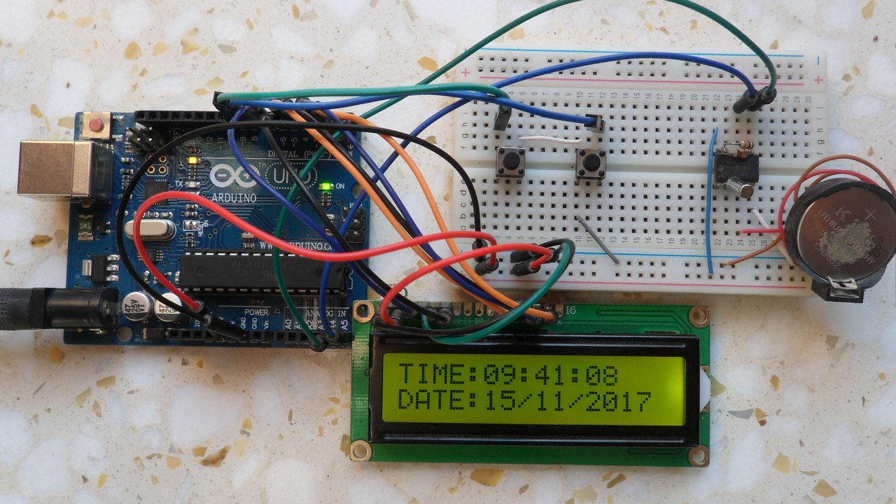
This post shows a simple real time clock and calendar example using an Arduino UNO board and DS1307 RTC chip where time and calendar are displayed on 1602 LCD screen and it can be set with two push buttons.
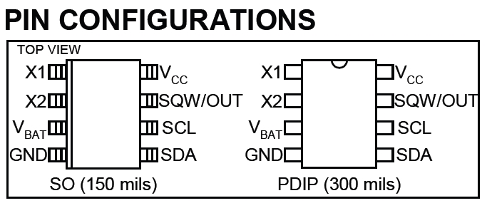
The DS1307 is an IC (integrated circuit) which has only 8 pins, it’s low cost, easy to use and it has the ability to count time and date in real time (more details are in the datasheet).
Hardware Required:
- Arduino board
- DS1307 RTC
- 16×2 LCD screen
- 32.768KHz crystal oscillator
- 2 x push button
- 2 x 10K ohm resistor
- 10K ohm variable resistor (or potentiometer)
- 330 ohm resistor
- 3V coin cell battery
- Breadboard
- Jumper wires
Arduino real time clock with DS1307 circuit:
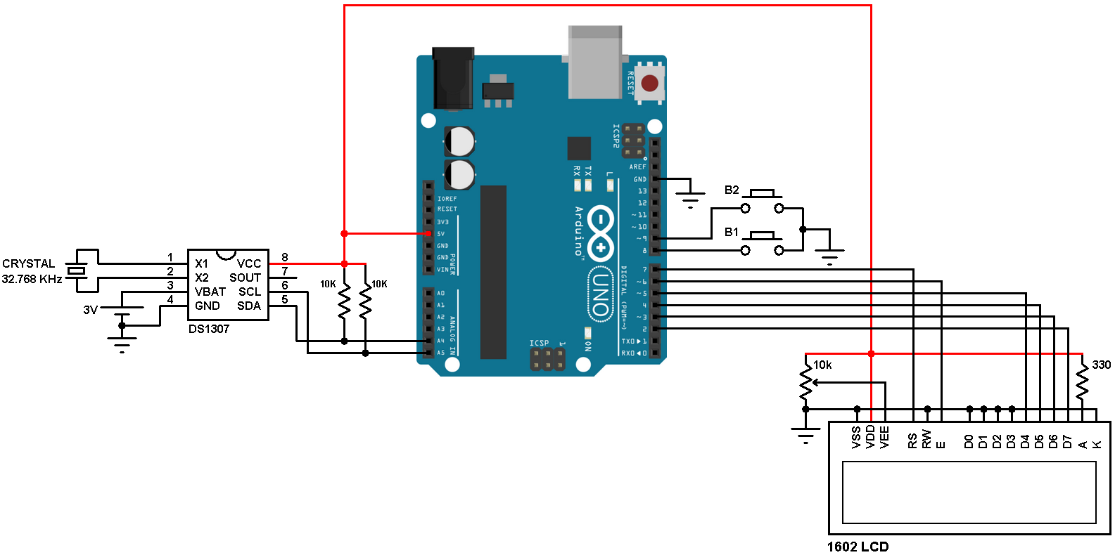
In the circuit there are 2 push buttons (B1 & B2) connected to pins 8 and 9 respectively, the two push buttons are used to set time date parameters (minutes, hours, date, month and year). Button B1 selects the parameter and B2 increments the selected parameter.
Arduino real time clock with DS1307 code:
The Arduino code below doesn’t use any library for the DS1307 RTC, the Wire library is for the communication between the Arduino and the DS1307 using I2C protocol.
The DS1307 works with BCD format only and to convert the BCD to decimal and vise versa I used the 2 lines below (example for minute):
// Convert BCD to decimal
minute = (minute >> 4) * 10 + (minute & 0x0F);
// Convert decimal to BCD
minute = ((minute / 10) << 4) + (minute % 10);
void DS1307_display() : displays time and calendar, before displaying time and calendar data are converted from BCD to decimal format.
void blink_parameter() : this small function works as a delay except that it is interrupted by the buttons B1 (connected to pin 8) and B2 (connected to pin 9). When called and without pressing any button the total time is 10 x 25ms = 250ms. With this function we can see the blinking of the selected parameter with a frequency of 2Hz. So a delay of 250ms comes after the print of the selected parameter and after that delay a 2 spaces is printed which makes the parameter disappears from the LCD and another 250ms delay comes after the print of the 2 spaces.
The complete code is below.
1 2 3 4 5 6 7 8 9 10 11 12 13 14 15 16 17 18 19 20 21 22 23 24 25 26 27 28 29 30 31 32 33 34 35 36 37 38 39 40 41 42 43 44 45 46 47 48 49 50 51 52 53 54 55 56 57 58 59 60 61 62 63 64 65 66 67 68 69 70 71 72 73 74 75 76 77 78 79 80 81 82 83 84 85 86 87 88 89 90 91 92 93 94 95 96 97 98 99 100 101 102 103 104 105 106 107 108 109 110 111 112 113 114 115 116 117 118 119 120 121 122 123 124 125 126 127 128 129 130 131 132 | // Real time clock and calendar with set buttons using DS1307 and Arduino // include LCD library code #include <LiquidCrystal.h> // include Wire library code (needed for I2C protocol devices) #include <Wire.h> // LCD module connections (RS, E, D4, D5, D6, D7) LiquidCrystal lcd(7, 6, 5, 4, 3, 2); void setup() { pinMode(8, INPUT_PULLUP); // button1 is connected to pin 8 pinMode(9, INPUT_PULLUP); // button2 is connected to pin 9 // set up the LCD's number of columns and rows lcd.begin(16, 2); Wire.begin(); // Join i2c bus } char Time[] = "TIME: : : "; char Calendar[] = "DATE: / /20 "; byte i, second, minute, hour, date, month, year; void DS1307_display(){ // Convert BCD to decimal second = (second >> 4) * 10 + (second & 0x0F); minute = (minute >> 4) * 10 + (minute & 0x0F); hour = (hour >> 4) * 10 + (hour & 0x0F); date = (date >> 4) * 10 + (date & 0x0F); month = (month >> 4) * 10 + (month & 0x0F); year = (year >> 4) * 10 + (year & 0x0F); // End conversion Time[12] = second % 10 + 48; Time[11] = second / 10 + 48; Time[9] = minute % 10 + 48; Time[8] = minute / 10 + 48; Time[6] = hour % 10 + 48; Time[5] = hour / 10 + 48; Calendar[14] = year % 10 + 48; Calendar[13] = year / 10 + 48; Calendar[9] = month % 10 + 48; Calendar[8] = month / 10 + 48; Calendar[6] = date % 10 + 48; Calendar[5] = date / 10 + 48; lcd.setCursor(0, 0); lcd.print(Time); // Display time lcd.setCursor(0, 1); lcd.print(Calendar); // Display calendar } void blink_parameter(){ byte j = 0; while(j < 10 && digitalRead(8) && digitalRead(9)){ j++; delay(25); } } byte edit(byte x, byte y, byte parameter){ char text[3]; while(!digitalRead(8)); // Wait until button (pin #8) released while(true){ while(!digitalRead(9)){ // If button (pin #9) is pressed parameter++; if(i == 0 && parameter > 23) // If hours > 23 ==> hours = 0 parameter = 0; if(i == 1 && parameter > 59) // If minutes > 59 ==> minutes = 0 parameter = 0; if(i == 2 && parameter > 31) // If date > 31 ==> date = 1 parameter = 1; if(i == 3 && parameter > 12) // If month > 12 ==> month = 1 parameter = 1; if(i == 4 && parameter > 99) // If year > 99 ==> year = 0 parameter = 0; sprintf(text,"%02u", parameter); lcd.setCursor(x, y); lcd.print(text); delay(200); // Wait 200ms } lcd.setCursor(x, y); lcd.print(" "); // Display two spaces blink_parameter(); sprintf(text,"%02u", parameter); lcd.setCursor(x, y); lcd.print(text); blink_parameter(); if(!digitalRead(8)){ // If button (pin #8) is pressed i++; // Increament 'i' for the next parameter return parameter; // Return parameter value and exit } } } void loop() { if(!digitalRead(8)){ // If button (pin #8) is pressed i = 0; hour = edit(5, 0, hour); minute = edit(8, 0, minute); date = edit(5, 1, date); month = edit(8, 1, month); year = edit(13, 1, year); // Convert decimal to BCD minute = ((minute / 10) << 4) + (minute % 10); hour = ((hour / 10) << 4) + (hour % 10); date = ((date / 10) << 4) + (date % 10); month = ((month / 10) << 4) + (month % 10); year = ((year / 10) << 4) + (year % 10); // End conversion // Write data to DS1307 RTC Wire.beginTransmission(0x68); // Start I2C protocol with DS1307 address Wire.write(0); // Send register address Wire.write(0); // Reset sesonds and start oscillator Wire.write(minute); // Write minute Wire.write(hour); // Write hour Wire.write(1); // Write day (not used) Wire.write(date); // Write date Wire.write(month); // Write month Wire.write(year); // Write year Wire.endTransmission(); // Stop transmission and release the I2C bus delay(200); // Wait 200ms } Wire.beginTransmission(0x68); // Start I2C protocol with DS1307 address Wire.write(0); // Send register address Wire.endTransmission(false); // I2C restart Wire.requestFrom(0x68, 7); // Request 7 bytes from DS1307 and release I2C bus at end of reading second = Wire.read(); // Read seconds from register 0 minute = Wire.read(); // Read minuts from register 1 hour = Wire.read(); // Read hour from register 2 Wire.read(); // Read day from register 3 (not used) date = Wire.read(); // Read date from register 4 month = Wire.read(); // Read month from register 5 year = Wire.read(); // Read year from register 6 DS1307_display(); // Diaplay time & calendar delay(50); // Wait 50ms } |
Arduino real time clock with DS1307 videos:
The video below shows a hardware circuit of the project.
and the second video shows Proteus simulation.
Downloads:
To be able to simulate this example, Proteus needs the Arduino library which can be downloaded from the link below. After extracting the files (ARDUINO.IDX and ARDUINO.LIB) put it in the Library folder (ex: C:\Program Files\Labcenter Electronics\Proteus 8 Professional\LIBRARY):
Download
Arduino + DS1307 + LCD Proteus simulation file download:
Download
Discover more from Simple Circuit
Subscribe to get the latest posts sent to your email.


Its showing wrong time for me, i copy pasted the code. Its showing the year 2050 and 62:06:42 as time
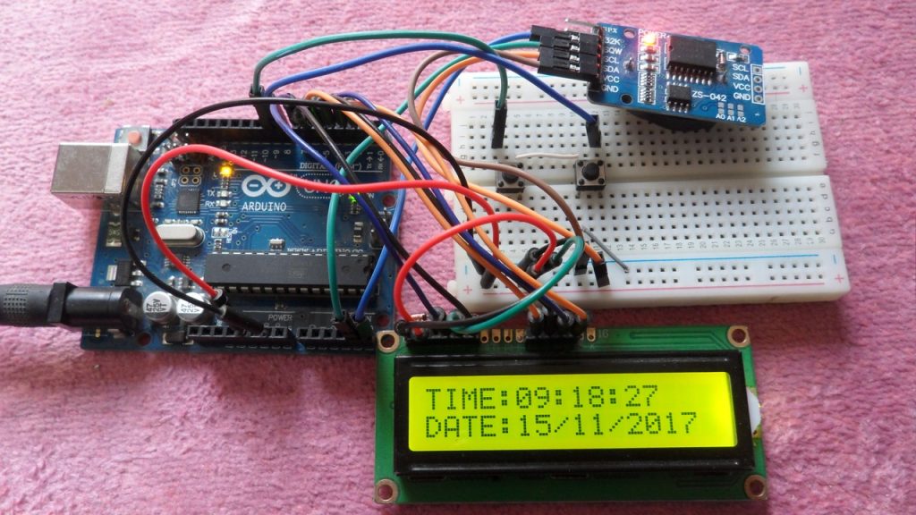
hi, how to use same method, but I’m using tiny RTC module?
Thanks. The clock project runs in Arduino. However, the set time is not stored in simulation. How to save the set time? Can one answer please! Thanks again.
Sir, How to write set date and time decrease button .(I am a beginner.)
After the end of the year press (Pin # 8), why is it all set to 00:00:00 date and time?
“minute /10 + 48 “ could you please explain this?
como seria con memoria eprom
Please help me move the date and month to 12,13 and 15,16 cells in the upper row. It doesn’t work. They still appear in cells 6.7 and 9.10. (25 07 in the photo) thank you in Advance.
https://drive.google.com/file/d/1n6AiXrvBuyQSp2Po40xGkp5ICY8PIani/view?usp=sharing
am not able to know that whether ds1307 rtc module gives the exact time when power supply is off and then on..??
How do you convert the 24 hr to 12 hr format?
WHICH BOARD YOU SELECTED TO COMPILE THE CODE ITS NOT WORKING WITH ARDUINO UNO
Try with latest Arduino IDE!
Will this work if i replace DS1307 library with DS1302 library and I2C address? Or there are more to do?
Actually I don’t know, read DS1302 & DS1307 datasheets and see what’re the differences, just make a try!
Can you please send me a code to set time and date by using buttons for DS1302 rtc??
Sorry, right now I’ve no example for the DS1302 RTC!
But it doesnt work.. I used DS1302. Time can be adjust by using buttons but it doesnt send to rtc
How to do this by using DS1302 rtc?
The easiest way is by using DS1302 RTC library!
help me.. Code files cannot be stored in hex ?
Try with this:
Open Arduino IDE, go to File –> Preferences –> Settings
Check: compilation
After you verify the code you will get ELF as well as HEX file paths at the bottom of the compilation box, for example:
C:\\Users\\NoName\\AppData\\Local\\Temp\\arduino_build_124983/sketch_nov12a.ino.elf
C:\\Users\\NoName\\AppData\\Local\\Temp\\arduino_build_124983/sketch_nov12a.ino.hex
You can copy each path using keyboard buttons Ctrl + P (after the selection of the path).
could you give me the whole code please
Full code is above, you can directly upload it to your Arduino board.
no meu caso estou usando um rtc ds 1302 e um display com i2c como ficaria? desde ja agradeço
Thanks for RTC Code
hi could you send me the whole code please bshimels88@gmail.com
Wrong link for Arduino + DS1307 + LCD Proteus simulation
Link updated. Thank you!