This post shows how to control a DC motor speed and direction of rotation using Arduino uno, joystick and L293D motor driver.
The joystick (PS2 Joystick) consists of two potentiometers (one for the X-axis and the other for the Y-axis) and a push-button. With one potentiometer we can control the speed and rotation direction of a DC motor.
The L293D quadruple half-H drivers chip allows us to drive 2 motors in both directions, with two PWM outputs from the Arduino we can easily control the speed as well as the direction of rotation of one DC motor. (PWM: Pulse Width Modulation).
Related topic:
Arduino DC motor speed and direction control with L293D
Components Required:
- Arduino UNO board —> datasheet
- 12V DC motor
- Joystick board
- L293D motor driver IC —> datasheet
- 12V source
- Breadboard
- Jumper wires
DC motor control with Arduino and joystick circuit:
Circuit schematic diagram is shown below.
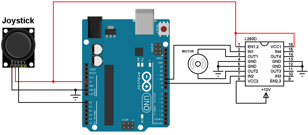
(All grounded terminals are connected)
The L293D driver has 2 VCCs: VCC1 is +5V (comes from the Arduino board) and VCC2 is +12V (same as motor nominal voltage). Pins IN1 and IN2 are the control pins where:
| IN1 | IN2 | Function |
| L | H | Direction 1 |
| H | L | Direction 2 |
| L | L | Fast motor stop |
| H | H | Fast motor stop |
As shown in the circuit diagram we need only 3 Arduino terminal pins: A0 (analog pin), pin 9 and pin 10. Pins 9 and 10 are PWM signal outputs, at any time there is only 1 active PWM, this allows us to control the direction of rotation as well as the speed by varying the duty cycle of the active PWM signal. The active PWM pin decides the motor direction of rotation (one at a time, the other output is logic 0).
The joystick board has 5 terminals: GND, +5V, VRX, VRY and SW where:
GND and +5V are power supply pins
VRX is the X-axis potentiometer output
VRY is the Y-axis potentiometer output
SW is the push button terminal (the other terminal is connected to GND).
The output of the X-axis potentiometer is connected to Arduino analog pin A0, Y-axis potentiometer output can be used to control the DC motor. The switch pin (SW) is not used in this example.
Using the X-axis and the Y-axis potentiometers we can control two DC motors independently.
Arduino code:
The resolution of the Arduino UNO ADC is 10 bits which means the digital output value is between 0 and 1023.
The PWM signals has a resolution of 8 bits which means the duty cycle can vary between 0 and 255.
1 2 3 4 5 6 7 8 9 10 11 12 13 14 15 16 17 18 19 20 21 22 23 24 25 26 27 28 29 30 | // Arduino joystick DC motor speed and rotation direction control #define joystick A0 #define pwm1 9 #define pwm2 10 int motor_control; void setup() { pinMode(pwm1, OUTPUT); pinMode(pwm2, OUTPUT); } void loop() { motor_control = analogRead(joystick); motor_control >>= 1; if(motor_control > 255){ digitalWrite(pwm2, 0); analogWrite(pwm1, (motor_control - 256)); } else if(motor_control < 255){ digitalWrite(pwm1, 0); analogWrite(pwm2, (255 - motor_control)); } else{ digitalWrite(pwm1, 0); digitalWrite(pwm2, 0); } } |
The video below shows a simple hardware circuit of the project:
Discover more from Simple Circuit
Subscribe to get the latest posts sent to your email.


