This electronic project shows how to generate a sine wave using Arduino board with the ability to control frequency and amplitude of the generated sinewave signal.
A two potentiometer connected to the Arduino board are used to control the amplitude and frequency of the sine wave signal ranging from 4Hz to 510Hz.
Creating a sinewave generator using Arduino UNO, or similar, board can be done by generating a PWM (Pulse Width Modulation) signal with the board microcontroller or using an external DAC (Digital-to-Analog Converter) if higher precision is needed. In this project we will use PWM technique for simplicity.
PWM Signal Overview:
A PWM Signal is just a square wave with a varied “on” and “off” times, or duty cycle, to approximate different voltage levels. When averaged over time, the PWM signal voltage values can behave as analog ones, but it is still a square wave signal.
The Arduino uno board microcontroller “ATmega328P” can generate high frequencies PWM signals with resolution up to 10 bits.
Duty_Cycle = [ON_Time/(ON_Time + OFF_Time)] * 100
Voltage = High_Voltage * Duty_Cycle
A PWM Signal can be smoothed to become a more continuous analog-like signal ranging from 0V to logic high (5V in case of Arduino uno board), the smoothing can be accomplished by a simple RC low pass filter. This filter reduces high-frequency components of the PWM signal, leaving behind a smoother signal that resembles the intended analog output, like a sine wave.
RC Low-Pass Filter:
An RC low-pass filter is a passive filter consists of two passive elements, a resistor (R) and a capacitor (C). It allows low-frequency signals to pass while attenuating higher frequencies, this smooths out the sharp transitions of a PWM signal.
The cutoff frequency, fc, of the RC low-pass filter determines which frequencies are allowed to pass. In other words, it is the frequency where the resistance and the capacitive reactance are equal.
The signal with frequency equals to the cutoff frequency is attenuated to 70.7%, or -3db, of its input voltage.
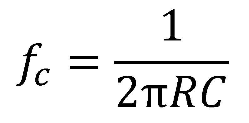
The cutoff frequency (fc) can be calculated using the equation below:
The low-pass RC filter can effectively smooth PWM signal. The key is to select appropriate resistor and capacitor values to filter out the high-frequency components of the PWM signal, leaving a cleaner approximation of an analog signal.
Arduino Sinewave Generator:
The Arduino uno board microcontroller ATmega328P does not have a built-in DAC (Digital-to-Analog Converter) module, but it can generate PWM signals using its Timer modules. In this project we will use PWM technique to create a controllable amplitude and frequency sinewave from a smoothed PWM signal.
Arduino Sinewave Generator Circuit:
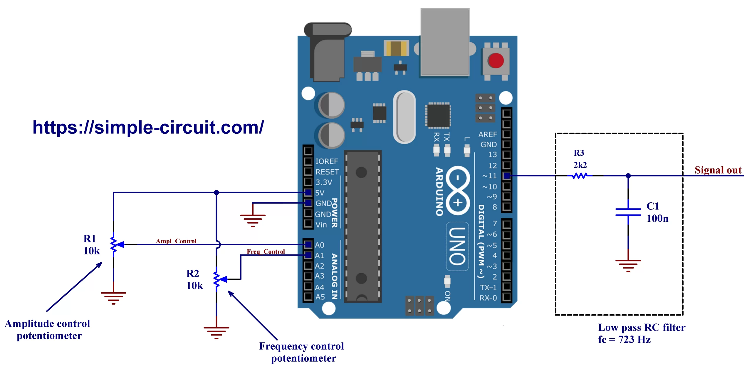
Project circuit diagram is shown below.
Hardware Required:
- Arduino uno, or similar, board —> Board details —> ATmega328P datasheet
- 2 x 10k potentiometer (R1, R2)
- 100nF ceramic capacitor (C1)
- 2.2k Ohm resistor (R3)
- Breadboard & jumper wires
Project circuit is very simple where few components are required, the Arduino board generates PWM signal on pin #11 which is then smoothed with resistor R3 and capacitor C1.
The cutoff frequency of this low pass filter is:
fc = 1/(2π * R3 * C1) = 1/(2π * 2.2k * 100n) = 723 Hz
Potentiometer R1 output is connected to Arduino analog channel 0 and it is used to control the amplitude of the output sinewave.
The second potentiometer R2 is connected to analog channel 1 and its is used to vary the frequency of the output sinewave signal ranging from 4Hz to 510Hz.
Arduino Sinewave Generator Code:
The Arduino code was tested with Arduino board containing the Microchip ATmega328P 8-bit microcontroller running @ 16MHz. Arduino UNO Rev 3, NANO Rev 3, and similar boards, contain this microcontroller chip.
Carrier Signal:
To get a sinewave using PWM technique, the duty cycle of the PWM signal has to be varied according to the analog voltage level of the wanted sinewave.
Timer2 module (8-bit Timer/Counter) is used to generate a PWM signal with frequency of 62.5kHz and resolution of 8 bits, this frequency is the highest frequency, with 8-bit resolution, the ATmega328P microcontroller can give @16Mhz clock input.
This PWM signal is the carrier signal of generated sinewave. Using a high frequency carrier PWM signal will significantly reduce the size of the smoothing low-pass filter.
Timer2 configuration are as follows:
1 2 3 4 5 | // Timer 2 configuration TCCR2A = 0x83; // Clear OC2A on Compare Match // Fast PWM mode TCCR2B = 0x01; // Timer clock = CLKio OCR2A = 127; // Initial duty cycle value (optional) |
With the above Timer 2 configuration, a PWM signal will be generated on Arduino pin #11 which is an Output Compare pin (OC2A). The frequency of the generated PWM signal can be calculated using the equation below:
f = CLKio/(Prescaler * 256) = 16MHz/(1 * 256) = 62.5kHz
The number 256 is where the Timer cleared (TOP value), or overflows, and at this value the Timer becomes 0 instead of 256. It also represents the resolution of the PWM signal where:
8 = log(256)/log(2).
Carrier signal duty cycle update:
To get a sinewave output (after smoothing) the duty cycle of the PWM signal need to be periodically updated. The value of the duty cycle is obtained from a lookup table array stored in the flash memory. This lookup table contains 100 values, this means for a one complete period of the generated sinewave the microcontroller have to update the PWM duty cycle 100 times.
1 | const uint8_t sineLookUpTable[] |
For example, if the output signal frequency is 100Hz, the period is 10ms, the duty cycle of the carrier PWM signal (62.5kHz) has to be updated every: 10ms/100 = 0.1ms = 100us.
To periodically update PWM carrier signal duty cycle, I used Timer1 (16-bit Timer/Counter) in CTC mode (Clear Timer on Compare match) with enabled interrupt. Changing this interrupt period will lead to a change in the output sinewave frequency, the interrupt period can be change by writing to the register OCR1A (Output Compare Register 1). Timer 1 is configured as shown below:
1 2 3 4 | // Timer 1 configuration TCCR1A = 0; TCCR1B = 0x09; // CTC mode (Clear Timer on Compare match) // Timer clock = CLKio |
For example, to get an output sinewave with 100Hz frequency, Timer1 module has to interrupt every 100us. This means Timer 1 has to reach the value stored in the OCR1A register (and therefor cleared) every 100us.
With current Timer1 configuration, the value of OCR1A register can be calculated using the following function:
OCR1A = 16MHz/( 100 * fsinewave )
and for 100Hz signal we get: OCR1A = 16MHz/(100 * 100) = 1600.
For an output sinewave signal of 4Hz:
OCR1A = 16MHz/(100 * 4) = 40000,
and for 510Hz:
OCR1A = 16MHz/(100 * 510) = 313.
To control the frequency of the generated sinewave, a potentiometer with output connected to Arduino analog channel 1 is used. To simplify the Arduino code, only 8 bits of analog data are used. This means that we have an 8-bit resolution carrier PWM signal (62.5kHz) and 8-bit resolution of ADC (Analog-to-Digital Converter).
Full Arduino Code:
1 2 3 4 5 6 7 8 9 10 11 12 13 14 15 16 17 18 19 20 21 22 23 24 25 26 27 28 29 30 31 32 33 34 35 36 37 38 39 40 41 42 43 44 45 46 47 48 49 50 51 52 53 54 55 56 57 58 59 60 61 62 63 64 65 66 67 68 69 70 71 72 73 74 75 76 77 78 79 80 81 82 83 | /**************************************************************************************** * * Sinewave generator using Arduino. * This is a free software with NO WARRANTY - Use it at your own risk! * https://simple-circuit.com/ * ***************************************************************************************/ const uint8_t sineLookUpTable[] = { 128, 136, 143, 151, 159, 167, 174, 182, 189, 196, 202, 209, 215, 220, 226, 231, 235, 239, 243, 246, 249, 251, 253, 254, 255, 255, 255, 254, 253, 251, 249, 246, 243, 239, 235, 231, 226, 220, 215, 209, 202, 196, 189, 182, 174, 167, 159, 151, 143, 136, 128, 119, 112, 104, 96, 88, 81, 73, 66, 59, 53, 46, 40, 35, 29, 24, 20, 16, 12, 9, 6, 4, 2, 1, 0, 0, 0, 1, 2, 4, 6, 9, 12, 16, 20, 24, 29, 35, 40, 46, 53, 59, 66, 73, 81, 88, 96, 104, 112, 119 }; void setup(void) { delay(1000); pinMode(11, OUTPUT); // configure pin 11 as output digitalWrite(11, LOW); // ADC configuration ADMUX = 0x60; // set ADC +ive reference to AVCC // use left adjusted ADC result presentation // select analog channel 0 ADCSRA = 0x87; // enable ADC module // set ADC prescaler to 128 --> ADC CLK = 125kHz // Timer 1 configuration TCCR1A = 0; TCCR1B = 0x09; // CTC mode (Clear Timer on Compare match) // Timer clock = CLKio // Timer 2 configuration TCCR2A = 0x83; // Clear OC2A on Compare Match // Fast PWM mode TCCR2B = 0x01; // Timer clock = CLKio OCR2A = 127; // Initial duty cycle value (optional) TIMSK1 = 0x02; // Enable Timer1 Output Compare A Match Interrupt } volatile uint8_t m = 128; uint8_t Pot1; // Timer1 Output Compare A Match Interrupt vector ISR(TIMER1_COMPA_vect) { OCR2A = ((uint16_t)sineLookUpTable[m] * Pot1) / 255; // Update PWM signal duty cycle m++; if(m > 99) m = 0; } // main loop void loop() { ADMUX &= 0xF0; // Select analog channel 0 ADCSRA |= (1 << ADSC); // Start a new ADC conversion while( ADCSRA & (1 << ADSC) ); // Wait for conversion complete Pot1 = ADCH; ADMUX |= 0x01; // Select analog channel 1 ADCSRA |= (1 << ADSC); // Start a new ADC conversion while( ADCSRA & (1 << ADSC) ); // Wait for conversion complete uint8_t Pot2 = ADCH; if(Pot2 < 2) Pot2 = 2; OCR1A = 160000/((uint16_t)2 * Pot2); // Update PWM frequency delay(100); // Wait 100 milliseconds } // end of code. |
Arduino Sinewave Generator Video:
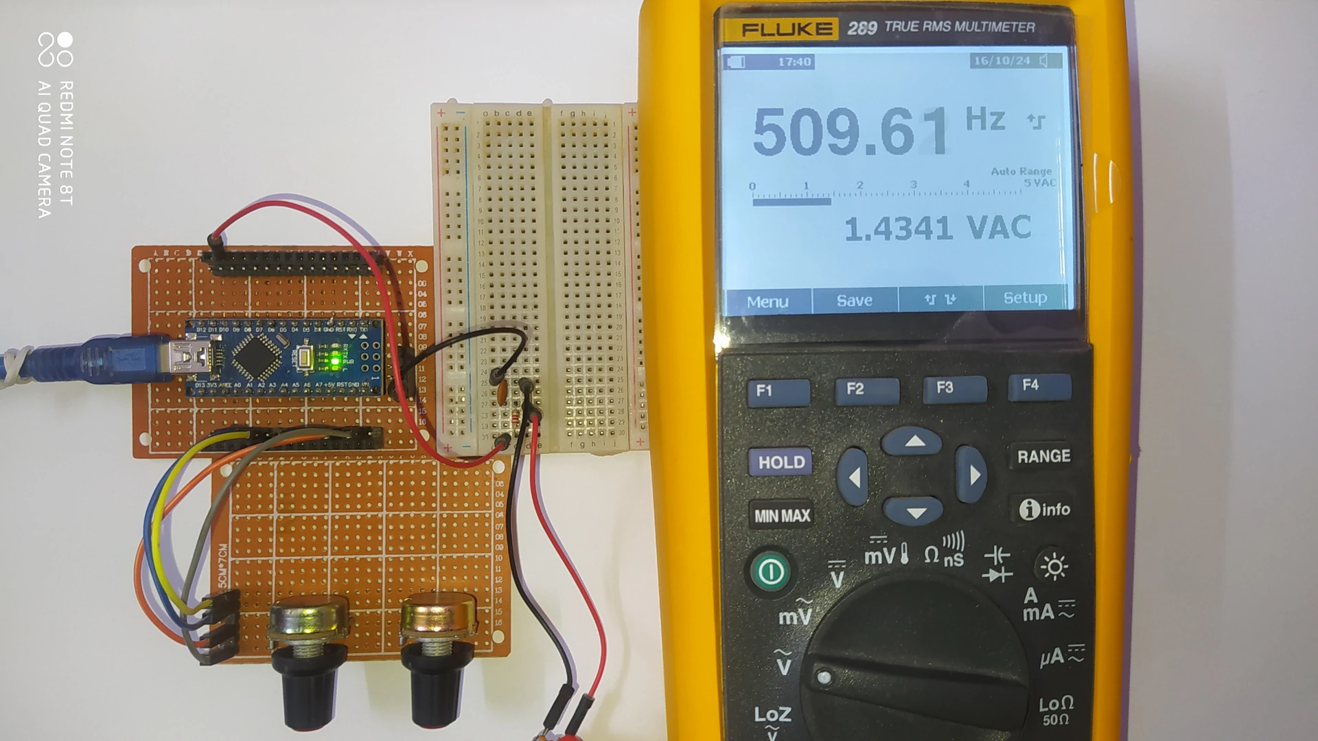
The video below shows Arduino sinewave generator circuit test where FLUKE 289 TRMS (True Root Mean Square) industrial multimeter is used to measure output signal amplitude and frequency.
As shown in the video there are two potentiometers, one for varying the amplitude and the second for varying the frequency of the output sinewave.
Second video shows the waveform of the output sinewave while varying amplitude and frequency of the signal. An oscilloscope is used to display the waveform.
Discover more from Simple Circuit
Subscribe to get the latest posts sent to your email.


this project has potential for making a pure sine wave inverter can you make one with feedback.thanks
Yes, that’s right.