The easiest way to control a sensorless BLDC motor is through an ESC (Electronic Speed Controller). This topic shows how to drive a BLDC motor using ESC and Microchip PIC16F887 microcontroller.
Topics related to this post:
PIC16F887 Timers and Interrupts
The basic components of the ESC is a microcontroller and at least 6 mosfets. It also consists of other components such as voltage regulator, capacitors, resistors ….. The controlling of the ESC is similar to the controlling of servo motor, the ESC controls the speed of the BLDC motor while the servo motor controller controls the position (moving angle) of a DC motor.
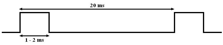
To drive the ESC or servo motor we’ve to provide a repeated 50Hz PWM signal (20 ms period) with a duty cycle between 5 and 10% (1 ms to 2 ms pulse). The following figure shows the PWM signal needed by the ESC:
Hardware Required:
- PIC16F887 microcontroller —> datasheet
- ESC (Electronic Speed Controller) __ I used 30A ESC
- Brushless DC motor __ I used 2210 – 1000KV BLDC motor
- 10K ohm potentiometer
- Breadboard
- Battery (or high power 12V source)
- Jumper wires
- PIC MCU programmer (PICkit 3, PICkit 4 …)
Sensorless brushless DC motor drive with an ESC and PIC16F887 circuit:
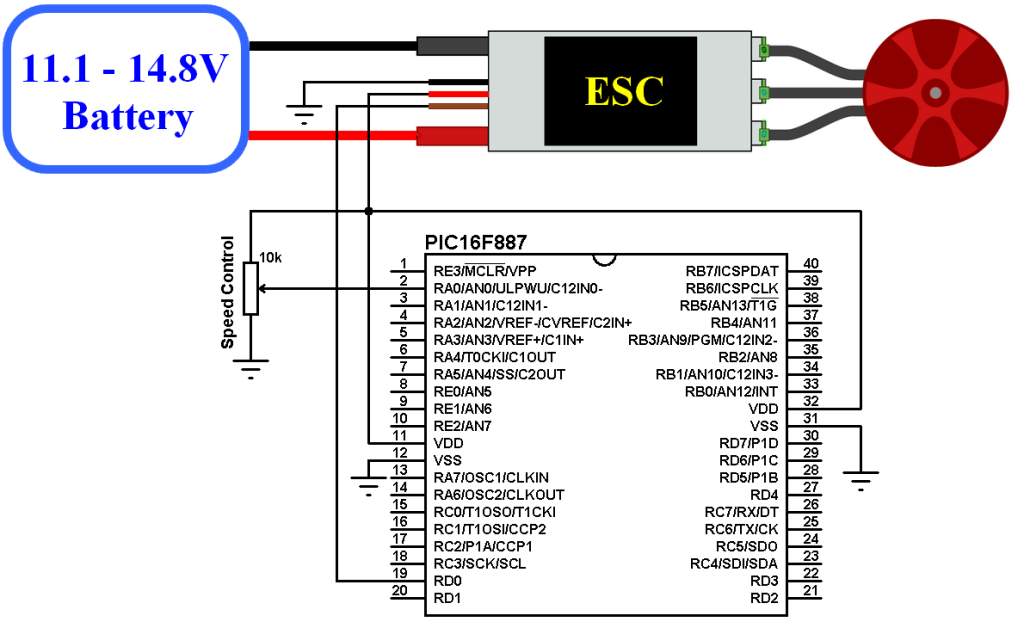
The two thick wires black and red are the ESC input power which normally comes from a battery (11.1V, 14.8V ….). There are also 3 thick wires which are black, red and brown (in my ESC white). The black and red are 5V voltage source which can be used to supply the microcontroller circuit as what I have done, or the microcontroller circuit can be supplied from an other source and in this case the red wire will not be used. The brown wire is the PWM signal wire and this wire is used to send PWM pulses from the microcontroller to the ESC through pin RD0.
In my hardware circuit I replaced the battery with 12V 10A DC voltage source.
The potentiometer which is connected to RA0 is used to control the speed of the BLDC motor.
In this example the PIC16F887 uses its internal oscillator and MCLR pin function is disabled.
Sensorless brushless DC motor drive with an ESC and PIC16F887 CCS C code:
Timer1 module is used to measure pulses width, it’s configured to increment every 1 us.
1 2 3 4 5 6 7 8 9 10 11 12 13 14 15 16 17 18 19 20 21 22 23 24 25 26 27 28 29 30 31 | /* Sensorless brushless DC motor drive with an ESC and PIC16F887 CCS PIC C code PIC16F887 runs with 8MHz internal oscillator */ #include <16F887.h> #device ADC = 10 #fuses NOMCLR, NOBROWNOUT, NOLVP, INTRC_IO #use delay(clock = 8MHz) #use fast_io(D) int16 i; void main(){ setup_oscillator(OSC_8MHZ); // Set internal oscillator to 8MHz output_d(0); set_tris_d(0); // Configure PORTD pins as outputs setup_adc(ADC_CLOCK_INTERNAL); // ADC module uses its internal oscillator setup_adc_ports(sAN0); // Configure AN0 as analog input pin set_adc_channel(0); setup_timer_1(T1_INTERNAL | T1_DIV_BY_2); // Setup Timer1 module: internal source + 2 prescaler while(TRUE){ set_timer1(0); // Set Timer1 value to 0 output_high(PIN_D0); i = read_adc(); // Read analog value from channel 0 and store it in 'i' if(i > 1000) i = 1000; i = i + 1000; while(get_timer1() < i); output_low(PIN_D0); while(get_timer1() < 19999); } } |
Example video:
Discover more from Simple Circuit
Subscribe to get the latest posts sent to your email.


// PIC 16F6887 , Hobbywings Skywalker 20A
// PORTB.F5 connected to test led
// PORTB.F6 connected to esc thruster signal port
// ESC VCC connected to 220AC – 12V DC 1.5 A Adaptor for trial
int i=0;
void main() {
ADCON0=0;
ADCON1 =0;
ANSEL=0;
ANSELH=0;
CM1CON0=0;
TRISA=0;
TRISB=0;
TRISC=0;
TRISD=0;
TRISE=0;
PORTA=0;
PORTB=0;
PORTC=0;
PORTD=0;
PORTE=0;
PORTB.F5=~PORTB.F5;
Delay_ms(500);
PORTB.F5=~PORTB.F5;
Delay_ms(500);
PORTB.F5=~PORTB.F5;
Delay_ms(500);
PORTB.F5=~PORTB.F5;
Delay_ms(500);
for (i=0; i<=500;i++){ // This to complete esc test period
PORTB.F6=1;
Delay_us(1000);
PORTB.F6=0;
Delay_us(19000);
}
PORTB.F5=~PORTB.F5;
Delay_ms(100);
PORTB.F5=~PORTB.F5;
Delay_ms(100);
PORTB.F5=~PORTB.F5;
Delay_ms(100);
PORTB.F5=~PORTB.F5;
Delay_ms(100);
PORTB.F5=~PORTB.F5;
Delay_ms(100);
PORTB.F5=~PORTB.F5;
Delay_ms(100);
PORTB.F5=~PORTB.F5;
Delay_ms(100);
PORTB.F5=~PORTB.F5;
Delay_ms(100);
while(1){
PORTB.F6=1;
Delay_us(1500); // can be set between low to high speed (1000-2000)
PORTB.F6=0;
Delay_us(18500); // 20000-speed range
}
}
Hi, I work on this project with PIC16F628A and I am created PWM signal but I am not using potentiometer. This my source code :
#include
#Fuses intrc_io,Nowdt,Nolvp,Noprotect
#use delay(clock=4MHz)
#use fast_io(b)
int16 i=500;
void main()
{
set_tris_b(0x00);
setup_timer_1(T1_INTERNAL | T1_DIV_BY_1);
output_b(0x00);
while(true)
{
set_timer1(0);
output_high(pin_b0);
if(i>1000)
i=1000;
i=i+1000;
while(get_timer1() < i);
output_low(pin_b0);
while(get_timer1() < 19999);
i=580;
}
}
I want to the motor turn constant speed but motor won't turn.Only when we quickly disconnect and connect the signal cable does the motor is turning for a short time. What you think this issue ?
Hi! I have the same problem as Samet Karasu. I use the same code but without using a potentiometer and read_adc().I try to use a constant value of i. But it seems that it’s not read by the ESC