The microcontroller PIC16F887 has many software and hardware interrupt routines and 3 timer modules which are: Timer0 (8-bit), Timer1 (16-bit) and Timer2 (8-bit). This topic shows how to use:
- External interrupt
- Interrupt-on-change pin (IOC)
- Timer0 and its interrupt
- Timer1 and its interrupt
- Timer2 and its interrupt
The first two are hardware interrupts whereas the others are software interrupts.
PIC16F887 External interrupt on pin RB0:
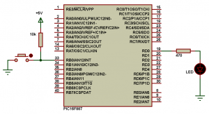
Let’s see how to toggle an LED connected to pin RA0 using the RB0 external interrupt. The external interrupt occurs when the RB0 button is pushed as shown in the circuit schematic below where the internal oscillator is used and MCLR pin function is disabled:
PIC16F887 External interrupt example CCS C code:
1 2 3 4 5 6 7 8 9 10 11 12 13 14 15 16 17 18 19 20 21 | /* PIC16F887 Microcontroller external interrupt example CCS C code Internal oscillator used @ 8MHz */ #include <16F887.h> #fuses NOMCLR NOBROWNOUT NOLVP INTRC_IO #use delay(clock = 8MHz) #INT_EXT void ext_isr(void){ clear_interrupt(INT_EXT); // Clear external interrupt flag bit output_toggle(PIN_D0); } void main(){ setup_oscillator(OSC_8MHZ); // Set the internal oscillator to 8MHz output_low(PIN_D0); clear_interrupt(INT_EXT); // Clear external interrupt flag bit enable_interrupts(INT_EXT_H2L); // Enable external interrupt enable_interrupts(GLOBAL); // Enable global interrupts while(TRUE); // Endless loop } |
The following video shows the working of the external interrupt (Proteus simulation):
PIC16F887 PORTB Interrupt-on-change (IOC):
All of the PORTB pins are individually configurable as an interrupt-on-change pin.
Example circuit schematic is shown below where there are 8 buttons and 8 LEDs. When we push a button the microcontroller will directly reads all PORTB pin status and displays the correspondent value on PORTD pins via the 8 LEDs.

PIC16F887 PORTB Interrupt-on-change example CCS C code:
1 2 3 4 5 6 7 8 9 10 11 12 13 14 15 16 17 18 19 20 21 | /* PIC16F887 Microcontroller PORTB interrupt-on-change example CCS C code Internal oscillator used @ 8MHz */ #include <16F887.h> #fuses NOMCLR NOBROWNOUT NOLVP INTRC_IO #use delay(clock = 8MHz) #INT_RB void ext_isr(void){ clear_interrupt(INT_RB); // Clear PORTB IOC flag bit output_d(input_b()); } void main(){ setup_oscillator(OSC_8MHZ); // Set the internal oscillator to 8MHz port_b_pullups(0xFF); // Enable all PORTB weak pull-ups clear_interrupt(INT_RB); // Clear PORTB IOC flag bit enable_interrupts(INT_RB); // Enable all PORTB IOC pins enable_interrupts(GLOBAL); // Enable global interrupts while(TRUE); // Endless loop } |
Example video:
PIC16F887 Timer0 module and interrupt:
The Timer0 module is an 8-bit timer/counter with the following features:
• 8-bit timer/counter register (TMR0)
• 8-bit prescaler (shared with Watchdog Timer)
• Programmable internal or external clock source
• Programmable external clock edge selection
• Interrupt on overflow
When used as a timer, the Timer0 module will increment every instruction cycle (prescaler = 1).
There are 8 prescaler options for the Timer0 module ranging from 1:2 to 1:256.
Timer0 will generate an interrupt when the TMR0 register overflows from FFh to 00h. The T0IF interrupt flag bit of the INTCON register is set every time the TMR0 register overflows, regardless of whether or not the Timer0 interrupt is enabled. The T0IF bit must be cleared in software. The Timer0 interrupt enable is the T0IE bit of the INTCON register.
Timer0 interrupt can be enabled using the following two commands:
enable_interrupts(INT_TIMER0) ;
enable_interrupts(GLOBAL) ;
The T0IF bit can be cleared using the command below:
clear_interrupt(INT_TIMER0) ;
We can set the timer0 preload value (initial value) using the following command:
set_timer0(preload_value) ;
where preload_value is an unsigned 8-bit number.
The clock source can be internal or external through RA4/T0CKI pin.
Timer0 prescaler rate and clock source and can be set using the following CCS line:
setup_timer_0(T0_INTERNAL | T0_DIV_256) ;
We can use the following equation to calculate Timer0 frequency:
Timer0_freq = MCU_freq / {4 * Prescaler * (256 – TMR0)}
where TMR0 is timer0 preload value.
and:
Period = 1/Timer0_freq which is time to interrupt.
PIC16F887 Timer1 module and interrupt:
The Timer1 module is a 16-bit timer/counter with the following features:
• 16-bit timer/counter register pair (TMR1H:TMR1L)
• Programmable internal or external clock source
• 3-bit prescaler
• Optional LP oscillator
• Synchronous or asynchronous operation
• Timer1 gate (count enable) via comparator or T1G pin
• Interrupt on overflow
• Wake-up on overflow (external clock, Asynchronous mode only)
• Time base for the Capture/Compare function
• Special Event Trigger (with ECCP)
• Comparator output synchronization to Timer1 clock
The TMR1 interrupt, if enabled, is generated on overflow which is latched in interrupt flag bit, TMR1IF (PIR1<0>). This interrupt can be enabled/disabled by setting/clearing TMR1 interrupt enable bit, TMR1IE (PIE1<0>).
Prescaler rate of the timer1 can be: 1, 2, 4 or 8.
The following equation computes timer1 frequency:
Timer1_freq = MCU_freq / {4 * Prescaler * (65536 – TMR1)}
Where TMR1 is preload value.
And Timer1 overflow time = 1/Timer1_freq
PIC16F887 Timer interrupts example (blink without delay):
This is a small example shows how to blink an LED connected to pin RA0 using timer interrupts.
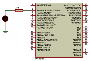
Circuit schematic is shown below:
LED Blink without delay using Timer0 module interrupt CCS C code:
1 2 3 4 5 6 7 8 9 10 11 12 13 14 15 16 17 18 19 20 21 22 23 24 25 26 27 28 29 30 | /* PIC16F887 Microcontroller Timer0 module interrupt example CCS C code Internal oscillator used @ 8MHz Timer0 period = 24.96 ms LED ON time = OFF time = 24.96 * 20 =~ 500 ms */ #include <16F887.h> #fuses NOMCLR NOBROWNOUT NOLVP INTRC_IO #use delay(clock = 8MHz) unsigned int8 n; #INT_TIMER0 void Timer0_isr(void){ n++; if(n > 19){ n = 0; output_toggle(PIN_A0); } set_timer0(61); // Timer0 preload value clear_interrupt(INT_TIMER0); // Clear Timer0 overflow bit } void main(){ setup_oscillator(OSC_8MHZ); // Set the internal oscillator to 8MHz clear_interrupt(INT_TIMER0); // Clear Timer0 overflow bit enable_interrupts(INT_TIMER0); // Enable Timer0 interrupt enable_interrupts(GLOBAL); // Enable global interrupts setup_timer_0(T0_INTERNAL | T0_DIV_256); // Timer0 configuration: internal clock source + 256 prescaler set_timer0(61); // Timer0 preload value while(TRUE); // Endless loop } |
LED Blink without delay using Timer1 module interrupt CCS C code:
1 2 3 4 5 6 7 8 9 10 11 12 13 14 15 16 17 18 19 20 21 22 23 24 | /* PIC16F887 Microcontroller Timer1 module interrupt example CCS C code Internal oscillator used @ 4MHz LED ON time = OFF time = 500 ms */ #include <16F887.h> #fuses NOMCLR NOBROWNOUT NOLVP INTRC_IO #use delay(clock = 4MHz) #INT_TIMER1 void Timer1_isr(void){ output_toggle(PIN_A0); set_timer1(3036); // Timer1 preload value clear_interrupt(INT_TIMER1); // Clear Timer1 overflow bit } void main(){ setup_oscillator(OSC_4MHZ); // Set the internal oscillator to 4MHz clear_interrupt(INT_TIMER1); // Clear Timer1 overflow bit enable_interrupts(INT_TIMER1); // Enable Timer1 interrupt enable_interrupts(GLOBAL); // Enable global interrupts setup_timer_1(T1_INTERNAL | T1_DIV_BY_8); // Timer1 configuration: internal clock source + 8 prescaler set_timer1(3036); // Timer1 preload value while(TRUE); // Endless loop } |
CCS and Proteus simulation files download link:
Download
Reference:
PIC16F887 datasheet from Microchip
Discover more from Simple Circuit
Subscribe to get the latest posts sent to your email.