This Arduino tutorial demonstrates how to interface an Arduino board with an SH1107 OLED display module featuring a 1.5-inch screen and a resolution of 128×128 pixels.
The project shows how to display text and draw basic shapes (such as circles and rectangles) on the SH1107 OLED, which is configured to operate in I2C mode.
Abbreviations:
OLED: Organic light Emitting Diode.
PLED: Polymer OLED.
TFT: Thin Film Transistor.
I2C: Inter-Integrated Circuit.
SPI: Serial Peripheral Interface.
IoT: Internet of things.
Overview of the SH1107 OLED Display Module:
The SH1107 chip is a CMOS OLED/PLED driver with controller commonly used in small to medium-sized Organic/Polymer light-emitting diode dot-matrix display systems.
The SH1107 chip supports a maximum display resolution of 128×128 pixel and it is designed to drive monochrome OLED panels and is widely used in embedded systems, IoT devices, and consumer electronics.
The SH1107 OLED display module is a compact monochrome graphic display module that uses the SH1107 driver chip. These display modules are typically 128×64 or 128×128 pixels and are commonly available in I2C or SPI communication interfaces. These displays are commonly found in small, low-power devices as they have high contrast, wide viewing angles, and compact size. They are often used in projects involving microcontrollers like Arduino, ESP32, Raspberry Pi, and others.
Properties of the SH1107 OLED Display Module:
- Resolution: Usually 128×64 or 128×128 pixels, smaller resolutions may be also available.
- Display Type: Monochrome (one color only that usually white, blue, or yellow pixels on a black background).
- Interface: Usually supports I2C and/or SPI communication with the I2C be the most common interface.
- Operating Voltage: Usually 3.3V or 5V, depending on the module.
- Power Consumption: Very low power usage as the display does not require backlight, making it ideal for battery-powered devices.
The image below shows an example of an SH1107 OLED display module that operates in I2C mode only:
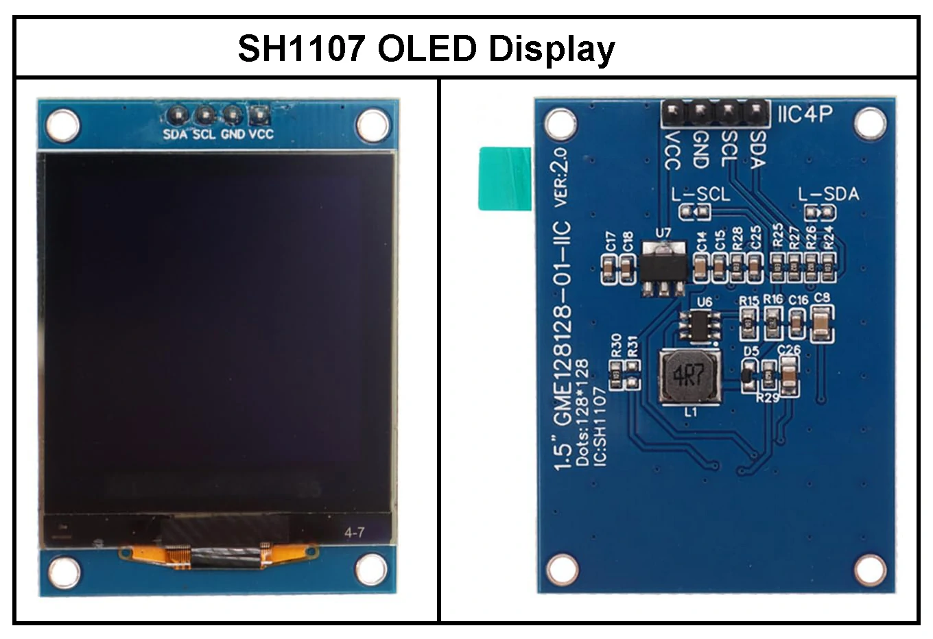
The SH1107 OLED display shown above operates using the I2C interface protocol only. Below is the pinout of the display module, which is essential for connecting it to a microcontroller such as an Arduino, ESP32, Raspberry Pi, or Microchip PIC/dsPIC:
- VCC: Power supply pin — typically 3.3V or 5V, depending on the module. Refer to your display’s datasheet to confirm the supported voltage. (Note: Some modules are 3.3V only.)
- GND: Ground pin, connected to circuit common ground.
- SCL: Serial Clock line of the I2C bus.
- SDA: Serial Data line of the I2C bus.
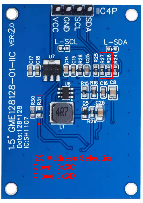
The default I2C address of this module is 0x3C, but it can be changed to 0x3D by shorting resistor R31, or by removing resistor R30 (10k) and placing it on R31 (see the image below).
Additionally, if you are using the same SH1107 display module shown above, it is better to replace resistors R26 and R27 (originally 1k each) with lower-value resistors not exceeding 100 Ohms —for example, use 33 Ohms.
Some SH1107 display modules support both I2C and SPI interface modes (one mode at a time), allowing users to switch between the two protocols with minor modifications to the module’s PCB.
The image below shows a module that supports both modes, where resistors R3 and R4 are used to select the desired protocol with SPI being the default.
To use the module in I2C mode, simply remove the 4.7 kΩ resistor from R3 and place it on R4.
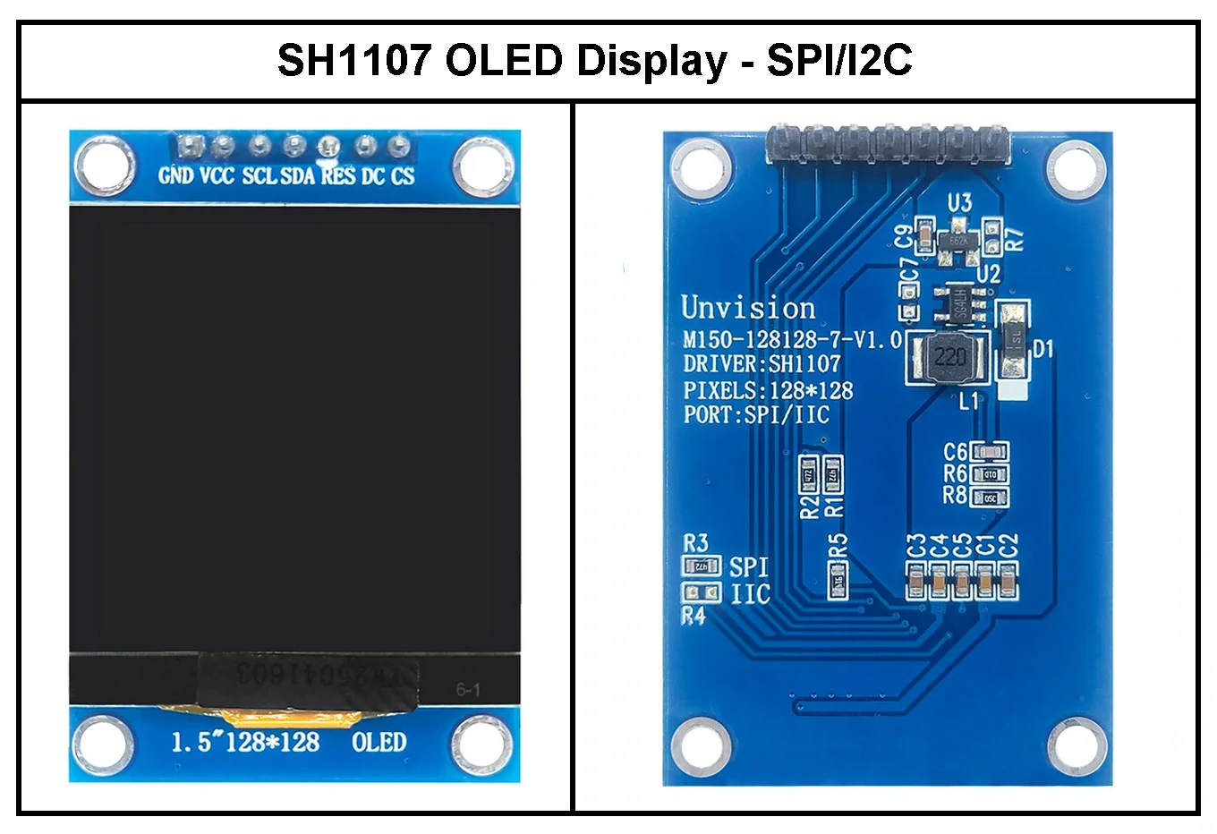
In the module shown above, the I2C address is determined by the connection of the DC pin:
- If DC pin is connected to GND, the address is 0x3C.
- If DC pin is connected to VCC, the address is 0x3D.
To operate the module in I2C mode:
- The RES (Reset) pin must either be connected to a digital I/O pin (if reset control is needed) or directly to VCC for a constant active state.
- The CS (Chip Select) pin must be connected to GND to properly enable I2C communication.

Interfacing Arduino Board with SH1107 OLED Display in I2C Mode:
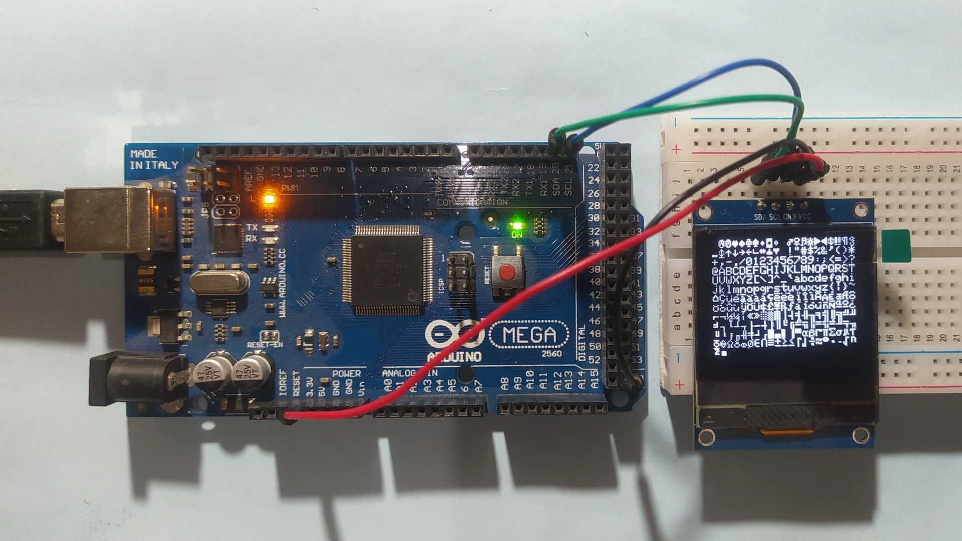
The images below show circuit schematic diagrams for interfacing an Arduino MEGA board with an SH1107 OLED display module.
The first schematic illustrates a display module that supports I2C mode only and cannot be used in SPI mode.
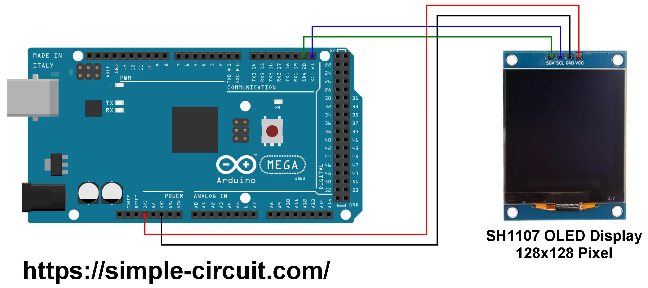
The SH1107 OLED display module used in the above schematic has four pins connected to the Arduino MEGA board as follows:
GND pin is connected to GND pin of the Arduino MEGA board.
VCC pin is connected to 3V3 pin of the Arduino MEGA board.
SDA (I2C serial data) is connected to digital pin 20 (SDA) on the Arduino MEGA.
SCL (I2C serial clock) is connected to digital pin 21 (SCL) on the Arduino MEGA.
- Note: Pins 20 and 21 on the Arduino MEGA are the hardware I2C pins of the ATmega2560 microcontroller, corresponding to the SDA and SCL lines, respectively.
The second schematic shows an SH1107 OLED display module that supports both SPI and I2C protocols, but is configured to operate in I2C mode:
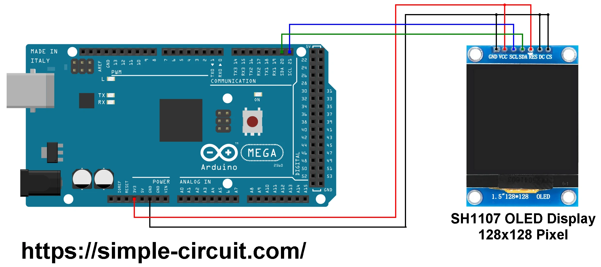
In this circuit schematic, the SH1107 OLED display module has seven pins connected to the Arduino MEGA board as follows:
GND pin is connected to GND pin of the Arduino MEGA board.
VCC pin is connected to 3V3 pin of the Arduino MEGA board.
SDA (I2C serial data) is connected to digital pin 20 (SDA) on the Arduino MEGA.
SCL (I2C serial clock) is connected to digital pin 21 (SCL) on the Arduino MEGA.
RES (Reset) pin is connected to VCC (3.3V).
DC (Data/Command) pin is connected to GND.
CS (Chip Select) is connected to GND.
Hardware Required:
This is a summary of the components needed to build this project:
- Arduino MEGA board (based on the ATmega2560 microcontroller – datasheet)
- SH1107 OLED display module (1.5-inch, 128×128 resolution)
- Bread board
- Jumper wires
Interfacing Arduino Board with SH1107 OLED Display in I2C Mode – Arduino Code:
To compile and run the Arduino code for this project, you’ll need to install two libraries from Adafruit Industries:
- Adafruit SH1107 OLED Display Library: This is the driver library for the SH1107 display. You can install it using the Arduino IDE Library Manager,
Go to Sketch → Include Library → Manage Libraries…, search for “sh1107”, and install the version published by Adafruit. - Adafruit GFX Library: This library provides graphics primitives (text, shapes, etc.) and is also available through the Library Manager. In the Arduino IDE Library Manager, Search for “Adafruit GFX” and install the library published by Adafruit.
Note: During the installation of the Adafruit SH1107 library, the Arduino IDE may prompt you to install additional dependency libraries (e.g., Adafruit BusIO)—make sure to accept and install them.
Tested Library Versions:
The following library versions were used to test and verify the project code:
- Adafruit GFX Library: Version 1.12.1
- Adafruit SH110X OLED Display Library: Version 2.1.13
- Adafruit BusIO: Version 1.17.1
Programming Hints:
The required libraries are included in the Arduino code as follows:
1 2 3 | #include <Wire.h> // I2C communication library #include <Adafruit_GFX.h> // Adafruit Graphics library #include <Adafruit_SH110X.h> // Adafruit SH110X display driver (supports SH1107) |
The SH1107 display is initialized with a resolution of 128×128 pixels and an I2C clock frequency of 400 kHz:
1 2 3 4 | #define SCREEN_WIDTH 128 // OLED display width, in pixels #define SCREEN_HEIGHT 128 // OLED display height, in pixels #define OLED_RESET -1 // can set an oled reset pin if desired Adafruit_SH1107 display = Adafruit_SH1107(SCREEN_WIDTH, SCREEN_HEIGHT, &Wire, OLED_RESET, 400000, 100000); |
Before using any display functions (e.g., print, drawLine, etc.), the SH1107 OLED display must be initialized. If the initialization fails, the screen will remain blank. Use the begin() function as shown below, specifying the appropriate I2C address:
1 | display.begin(0x3C, true); // Try 0x3D if the display does not respond at 0x3C |
Note: The Arduino code provided below is based on an example sketch from the Adafruit SH1107 library. Minor modifications were made to adapt it to this project setup.
Full Arduino code:
1 2 3 4 5 6 7 8 9 10 11 12 13 14 15 16 17 18 19 20 21 22 23 24 25 26 27 28 29 30 31 32 33 34 35 36 37 38 39 40 41 42 43 44 45 46 47 48 49 50 51 52 53 54 55 56 57 58 59 60 61 62 63 64 65 66 67 68 69 70 71 72 73 74 75 76 77 78 79 80 81 82 83 84 85 86 87 88 89 90 91 92 93 94 95 96 97 98 99 100 101 102 103 104 105 106 107 108 109 110 111 112 113 114 115 116 117 118 119 120 121 122 123 124 125 126 127 128 129 130 131 132 133 134 135 136 137 138 139 140 141 142 143 144 145 146 147 148 149 150 151 152 153 154 155 156 157 158 159 160 161 162 163 164 165 166 167 168 169 170 171 172 173 174 175 176 177 178 179 180 181 182 183 184 185 186 187 188 189 190 191 192 193 194 195 196 197 198 199 200 201 202 203 204 205 206 207 208 209 210 211 212 213 214 215 216 217 218 219 220 221 222 223 224 225 226 227 228 229 230 231 232 233 234 235 236 237 238 239 240 241 242 243 244 245 246 247 248 249 250 251 252 253 254 255 256 257 258 259 260 261 262 263 264 265 266 267 268 269 270 271 272 273 274 275 276 277 278 279 280 281 282 283 284 285 286 287 288 289 290 291 292 293 294 295 296 297 298 299 300 301 302 303 304 305 306 307 308 309 310 311 312 313 314 315 316 317 318 319 320 321 322 323 324 325 326 327 328 329 330 331 332 333 334 335 336 337 338 339 340 341 342 343 344 345 346 347 348 349 350 351 352 353 354 355 356 357 358 359 360 361 362 363 364 365 366 367 368 369 370 371 372 373 374 375 376 377 378 379 380 381 382 383 384 385 386 387 388 389 390 | /****************************************************************************** * Interfacing Arduino MEGA board with SH1107 OLED monochrome display. * The SSH1107 OLED resolution is 128x128 Pixel and it is configured to work * in I2C mode with address 0x3C (0x78). * This is a free software with NO WARRANTY. * https://simple-circuit.com/ /*******************************************************************************/ #include <Wire.h> // I2C communication library #include <Adafruit_GFX.h> // Adafruit Graphics library #include <Adafruit_SH110X.h> // Adafruit SH110X display driver (supports SH1107) #define SCREEN_WIDTH 128 // OLED display width, in pixels #define SCREEN_HEIGHT 128 // OLED display height, in pixels #define OLED_RESET -1 // Set to -1 if no reset pin is used Adafruit_SH1107 display = Adafruit_SH1107(SCREEN_WIDTH, SCREEN_HEIGHT, &Wire, OLED_RESET, 400000, 100000); #define LOGO_HEIGHT 16 #define LOGO_WIDTH 16 static const unsigned char PROGMEM logo_bmp[] = { 0b00000000, 0b11000000, 0b00000001, 0b11000000, 0b00000001, 0b11000000, 0b00000011, 0b11100000, 0b11110011, 0b11100000, 0b11111110, 0b11111000, 0b01111110, 0b11111111, 0b00110011, 0b10011111, 0b00011111, 0b11111100, 0b00001101, 0b01110000, 0b00011011, 0b10100000, 0b00111111, 0b11100000, 0b00111111, 0b11110000, 0b01111100, 0b11110000, 0b01110000, 0b01110000, 0b00000000, 0b00110000 }; void setup() { Serial.begin(9600); delay(500); // wait for the OLED to power up // Show image buffer on the display hardware. // Since the buffer is intialized with an Adafruit splashscreen // internally, this will display the splashscreen. display.begin(0x3C, true); // Try 0x3D if the display does not respond at 0x3C //display.setContrast (0); // dim display display.display(); delay(2000); // Clear the buffer. display.clearDisplay(); // draw a single pixel display.drawPixel(10, 10, SH110X_WHITE); // Show the display buffer on the hardware. // NOTE: You _must_ call display after making any drawing commands // to make them visible on the display hardware! display.display(); delay(2000); display.clearDisplay(); testdrawline(); // Draw many lines testdrawrect(); // Draw rectangles (outlines) testfillrect(); // Draw rectangles (filled) testdrawcircle(); // Draw circles (outlines) testfillcircle(); // Draw circles (filled) testdrawroundrect(); // Draw rounded rectangles (outlines) testfillroundrect(); // Draw rounded rectangles (filled) testdrawtriangle(); // Draw triangles (outlines) testfilltriangle(); // Draw triangles (filled) testdrawchar(); // Draw characters of the default font testdrawstyles(); // Draw 'stylized' characters testdrawbitmap(); // Draw a small bitmap image testanimate(logo_bmp, LOGO_WIDTH, LOGO_HEIGHT); // Animate bitmaps } void loop() { } void testdrawline() { int16_t i; display.clearDisplay(); // Clear display buffer for(i=0; i<display.width(); i+=4) { display.drawLine(0, 0, i, display.height()-1, SH110X_WHITE); display.display(); // Update screen with each newly-drawn line delay(1); } for(i=0; i<display.height(); i+=4) { display.drawLine(0, 0, display.width()-1, i, SH110X_WHITE); display.display(); delay(1); } delay(250); display.clearDisplay(); for(i=0; i<display.width(); i+=4) { display.drawLine(0, display.height()-1, i, 0, SH110X_WHITE); display.display(); delay(1); } for(i=display.height()-1; i>=0; i-=4) { display.drawLine(0, display.height()-1, display.width()-1, i, SH110X_WHITE); display.display(); delay(1); } delay(250); display.clearDisplay(); for(i=display.width()-1; i>=0; i-=4) { display.drawLine(display.width()-1, display.height()-1, i, 0, SH110X_WHITE); display.display(); delay(1); } for(i=display.height()-1; i>=0; i-=4) { display.drawLine(display.width()-1, display.height()-1, 0, i, SH110X_WHITE); display.display(); delay(1); } delay(250); display.clearDisplay(); for(i=0; i<display.height(); i+=4) { display.drawLine(display.width()-1, 0, 0, i, SH110X_WHITE); display.display(); delay(1); } for(i=0; i<display.width(); i+=4) { display.drawLine(display.width()-1, 0, i, display.height()-1, SH110X_WHITE); display.display(); delay(1); } delay(2000); // Pause for 2 seconds } void testdrawrect(void) { display.clearDisplay(); for(int16_t i=0; i<display.height()/2; i+=2) { display.drawRect(i, i, display.width()-2*i, display.height()-2*i, SH110X_WHITE); display.display(); // Update screen with each newly-drawn rectangle delay(1); } delay(2000); } void testfillrect(void) { display.clearDisplay(); for(int16_t i=0; i<display.height()/2; i+=3) { // The INVERSE color is used so rectangles alternate white/black display.fillRect(i, i, display.width()-i*2, display.height()-i*2, SH110X_INVERSE); display.display(); // Update screen with each newly-drawn rectangle delay(1); } delay(2000); } void testdrawcircle(void) { display.clearDisplay(); for(int16_t i=0; i<max(display.width(),display.height())/2; i+=2) { display.drawCircle(display.width()/2, display.height()/2, i, SH110X_WHITE); display.display(); delay(1); } delay(2000); } void testfillcircle(void) { display.clearDisplay(); for(int16_t i=max(display.width(),display.height())/2; i>0; i-=3) { // The INVERSE color is used so circles alternate white/black display.fillCircle(display.width() / 2, display.height() / 2, i, SH110X_INVERSE); display.display(); // Update screen with each newly-drawn circle delay(1); } delay(2000); } void testdrawroundrect(void) { display.clearDisplay(); for(int16_t i=0; i<display.height()/2-2; i+=2) { display.drawRoundRect(i, i, display.width()-2*i, display.height()-2*i, display.height()/4, SH110X_WHITE); display.display(); delay(1); } delay(2000); } void testfillroundrect(void) { display.clearDisplay(); for(int16_t i=0; i<display.height()/2-2; i+=2) { // The INVERSE color is used so round-rects alternate white/black display.fillRoundRect(i, i, display.width()-2*i, display.height()-2*i, display.height()/4, SH110X_INVERSE); display.display(); delay(1); } delay(2000); } void testdrawtriangle(void) { display.clearDisplay(); for(int16_t i=0; i<max(display.width(),display.height())/2; i+=5) { display.drawTriangle( display.width()/2 , display.height()/2-i, display.width()/2-i, display.height()/2+i, display.width()/2+i, display.height()/2+i, SH110X_WHITE); display.display(); delay(1); } delay(2000); } void testfilltriangle(void) { display.clearDisplay(); for(int16_t i=max(display.width(),display.height())/2; i>0; i-=5) { // The INVERSE color is used so triangles alternate white/black display.fillTriangle( display.width()/2 , display.height()/2-i, display.width()/2-i, display.height()/2+i, display.width()/2+i, display.height()/2+i, SH110X_INVERSE); display.display(); delay(1); } delay(2000); } void testdrawchar(void) { display.clearDisplay(); display.setTextSize(1); // Normal 1:1 pixel scale display.setTextColor(SH110X_WHITE); // Draw white text display.setCursor(0, 0); // Start at top-left corner display.cp437(true); // Use full 256 char 'Code Page 437' font // Not all the characters will fit on the display. This is normal. // Library will draw what it can and the rest will be clipped. for(int16_t i=0; i<256; i++) { if(i == '\n') display.write(' '); else display.write(i); } display.display(); delay(2000); } void testdrawstyles(void) { display.clearDisplay(); display.setTextSize(1); // Normal 1:1 pixel scale display.setTextColor(SH110X_WHITE); // Draw white text display.setCursor(0,0); // Start at top-left corner display.println(F("Hello, world!")); display.setTextColor(SH110X_BLACK, SH110X_WHITE); // Draw 'inverse' text display.println(3.141592); display.setTextSize(2); // Draw 2X-scale text display.setTextColor(SH110X_WHITE); display.print(F("0x")); display.println(0xDEADBEEF, HEX); display.display(); delay(2000); } void testdrawbitmap(void) { display.clearDisplay(); display.drawBitmap( (display.width() - LOGO_WIDTH ) / 2, (display.height() - LOGO_HEIGHT) / 2, logo_bmp, LOGO_WIDTH, LOGO_HEIGHT, 1); display.display(); delay(1000); } #define NUMFLAKES 10 #define XPOS 0 // Indexes into the 'icons' array in function below #define YPOS 1 #define DELTAY 2 #define DELTAT 3 void testanimate(const uint8_t *bitmap, uint8_t w, uint8_t h) { uint8_t f; int16_t icons[NUMFLAKES][4]; // Initialize 'snowflake' positions for(f = 0; f < NUMFLAKES; f++) { icons[f][XPOS] = random(1 - LOGO_WIDTH, display.width()); icons[f][YPOS] = -LOGO_HEIGHT; icons[f][DELTAY] = random(1, 8); icons[f][DELTAT] = 0; Serial.print(F("x: ")); Serial.print(icons[f][XPOS], DEC); Serial.print(F(" y: ")); Serial.print(icons[f][YPOS], DEC); Serial.print(F(" dy: ")); Serial.println(icons[f][DELTAY], DEC); } display.clearDisplay(); // Clear the display buffer for(;;) { // Loop forever... // Draw each snowflake: for(f=0; f< NUMFLAKES; f++) { icons[f][DELTAT] += 1; if (icons[f][DELTAT] >= icons[f][DELTAY]) { icons[f][YPOS] += 1; icons[f][DELTAT] = 0; display.drawBitmap(icons[f][XPOS], icons[f][YPOS] - 1, bitmap, w, h, SH110X_BLACK); // Erase the snowflake display.drawBitmap(icons[f][XPOS], icons[f][YPOS], bitmap, w, h, SH110X_WHITE); } } display.display(); // Show the display buffer on the screen delay(40); // Pause for 40 ms // Then update coordinates of each flake... for(f = 0; f < NUMFLAKES; f++) { //icons[f][YPOS] += icons[f][DELTAY]; // If snowflake is off the bottom of the screen... if (icons[f][YPOS] >= (display.height())) { // Reinitialize to a random position, just off the top icons[f][XPOS] = random(1 - LOGO_WIDTH, display.width()); icons[f][YPOS] = -LOGO_HEIGHT; icons[f][DELTAY] = random(1, 8); icons[f][DELTAT] = 0; } } } } // End of code. // https://simple-circuit.com/ /********************************************************************* This is an example for our Monochrome OLEDs based on SH1107 drivers This example is for a 128x128 size display using I2C to communicate Adafruit invests time and resources providing this open source code, please support Adafruit and open-source hardware by purchasing products from Adafruit! Written by Limor Fried/Ladyada for Adafruit Industries. BSD license, check license.txt for more information All text above, and the splash screen must be included in any redistribution *********************************************************************/ |
Interfacing Arduino Board with SH1107 OLED Display in I2C Mode – Video:
The video below demonstrates the interfacing of an Arduino MEGA board with an SH1107 OLED display using I2C communication.
Related Project:
Interfacing Arduino with SH1107 OLED Display in SPI Mode
Discover more from Simple Circuit
Subscribe to get the latest posts sent to your email.


