Adding a display to an electronic circuit can significantly enhance the functionality, usability, and overall user experience of the electronic project. Whether it’s a simple LCD, an OLED display, or a TFT screen, displays provide visual feedback and interaction capabilities between the circuit and human that are essential for many applications.
As an addition to the above, adding a display to an electronic circuit can help solve project code issues.
This Arduino tutorial shows how to interface Arduino UNO board with SSD1331 color OLED display module that has a size of 0.95-inch and resolution of 96×64 pixel.
The example shows how to print texts and draw shapes (circles, rectangular…) on the SSD1331 OLED display.
Abbreviations:
LCD: Liquid Crystal Display.
OLED: Organic light Emitting Diode.
PLED: Polymer OLED.
TFT: Thin Film Transistor.
SPI: Serial Peripheral Interface.
IoT: Internet of things.
The SSD1331 Color OLED Display Module:
The SSD1331 is a popular OLED/PLED display controller chip commonly used in small colored OLED displays. It supports a maximum resolution of 96×64 pixels and can drive RGB (Red, Green, Blue) OLED panels.
The SSD1331 OLED display module is a compact, color OLED display module that uses the SSD1331 controller. It typically has a resolution of 96×64 pixels and supports 16-bit color (65K colors).
The SSD1331 color OLED display is often used in applications where small, low-power displays are required.
The SSD1331 OLED display module used in this project is the one below:
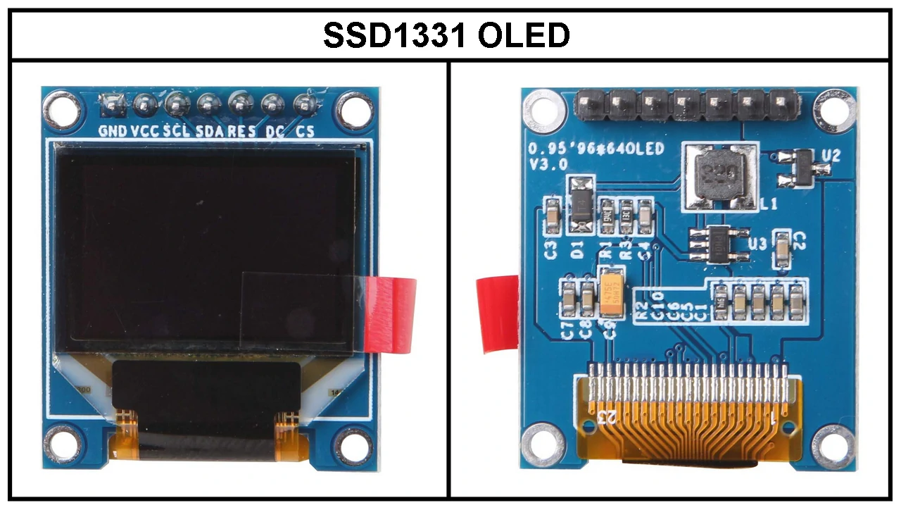
The SSD1331 display shown above works with SPI interface mode and has 7 pins. Below is the pinout for the display module, which is essential for connecting it to a microcontroller like Arduino, ESP32, Raspberry Pi, or Microchip PIC.
- GND: Ground pin, connected to circuit common ground.
- VCC: Power supply pin, may be 3.3V or 5V (refer to your display datasheet for power supply voltage range, some modules works only with 3.3V).
- SCL: Serial clock pin for the SPI interface. Connected to the SPI clock pin (SCK) of the microcontroller.
- SDA: Serial data pin for the SPI interface. Connected to the SPI data pin (MOSI) of the microcontroller.
- RES: Reset pin. Used to reset the display. If used, it is connected to any general purpose output pin of the microcontroller.
- DC: Data/Command selection pin. Connected to a digital output pin on the microcontroller. It determines whether the data on the bus is a command or actual pixel data.
- CS: Chip Select pin (active low). Connected to a digital pin on the microcontroller. Used to enable or disable the communication with the SSD1331 OLED display.
Interfacing Arduino with SSD1331 Color OLED Display:
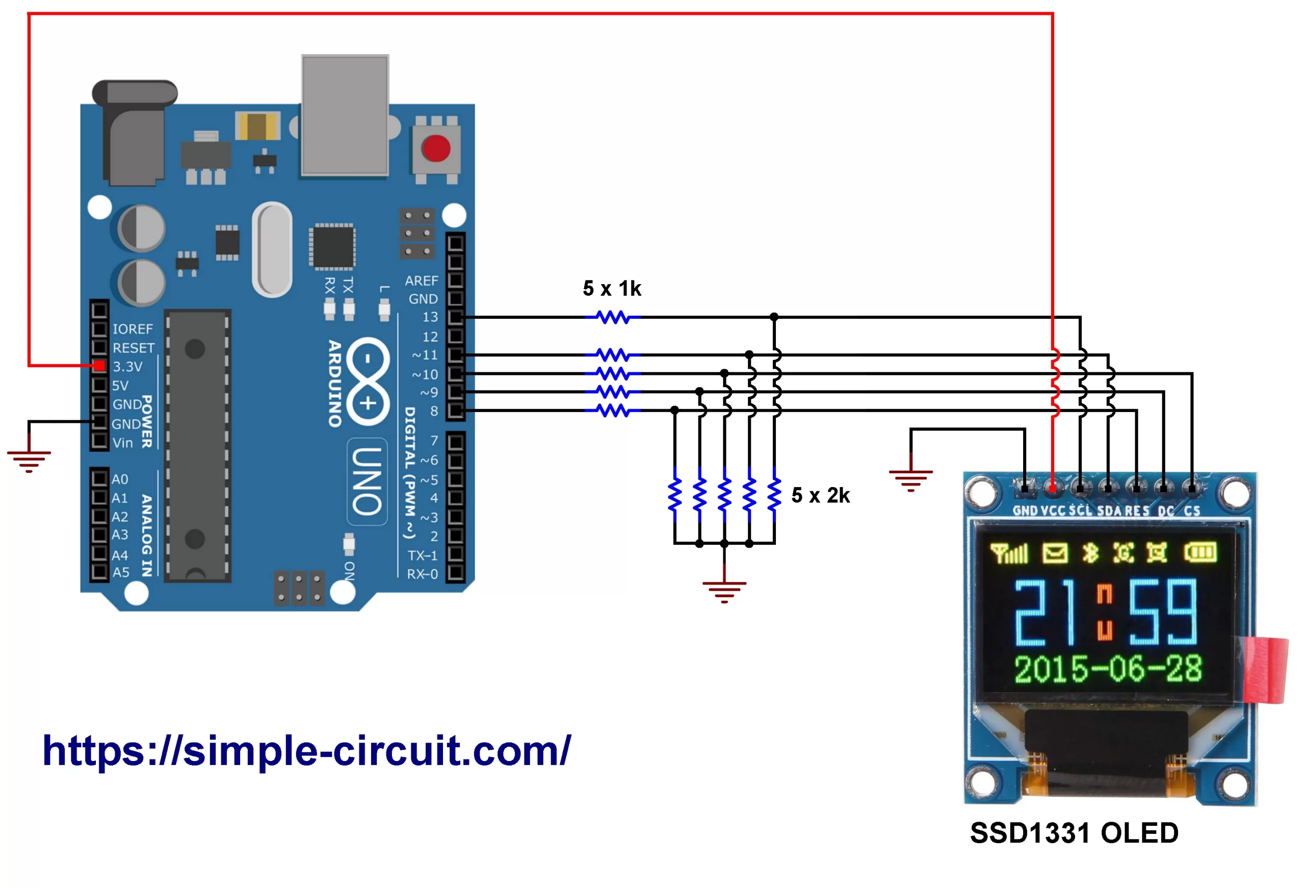
This post shows how to interface Arduino board with SSD1331 OLED display. Circuit diagram is shown below.
The SSD1331 color OLED display module shown in project wiring diagram has 7 pins: (from left to right): GND (ground), VCC, SCL (serial clock), SDA (serial data), RES (reset), DC (data/command), and CS (chip select).
Hardware Required:
Required parts are listed below.
- Arduino UNO (or similar) board —> Board details
- SSD1331 OLED display module
- 5 x 2k ohm resistor
- 5 x 1k ohm resistor
- Breadboard
- Jumper wires
Since the SSD1331 OLED display operates at 3.3V logic level and the Arduino uno board at 5V, I used a resistive voltage divider to reduce the 5V output of the Arduino to about 3.3V.
The resistive voltage divider may be the simplest method, but other more efficient ways can be used such as using logic level shifters.
As we have 5 data lines between the Arduino board and the SSD1331 display there are also 5 resistive voltage divider where each one is implemented with two resistors of 1k and 2k.
Connecting a 5V microcontroller directly to the SSD1331 OLED display violates the electrical characteristics written in the display datasheet and may damage the controller circuit of the display.
The SSD1331 display module is supplied with 3.3V from the Arduino board where:
- GND pin of the SSD1331 display is connected to GND pin of the Arduino board, and
- VCC pin of the display is connected to pin 3.3V of the Arduino board.
Other pins are connected as follows (each one through voltage divider):
- SCL pin is connected to Arduino digital pin 13.
- SDA pin is connected to Arduino digital pin 11.
- RES pin is connected to Arduino digital pin 8.
- DC pin is connected to Arduino digital pin 9.
- CS pin is connected to Arduino digital pin 10.
Note that pins 13 and 11 of the Arduino uno and similar boards are hardware SPI pins of the ATmega328P microcontroller, for SCK (Serial Clock) and MOSI (Master-Out Slave-In), respectively.
Interfacing Arduino with SSD1331 Color OLED Display Code:
Project Arduino code is just an example of graphics test provided by Adafruit Industries, with some modifications.
To be able to compile project Arduino code, two libraries from Adafruit Industries are required:
The first library is a driver for the SSD1331 OLED display and it can be installed from Arduino IDE library manager (Sketch —> Include Library —> Manage Libraries…, in the search box write “ssd1331” and install the one from Adafruit).
The second library is Adafruit graphics library which can be installed also from Arduino IDE library manager.
During the installation of the Adafruit SSD1331 display library, Arduino IDE may ask for installing some other libraries form Adafruit Industries (dependencies).
Project code was tested with the following library versions:
Adafruit GFX Library: Version 1.11.11.
Adafruit SSD1331 OLED driver: Version 1.2.2.
Adafruit BusIO: Version 1.17.0.
The used libraries are included in the Arduino code as shown below:
1 2 3 | #include <Adafruit_GFX.h> // Adafruit Graphics library #include <Adafruit_SSD1331.h> // Adafruit SSD1331 display driver #include <SPI.h> // Arduino SPI library |
The connection between the SSD1331 display and the Arduino board is as shown in the above wiring diagram, it is defined in the Arduino code as shown below:
1 2 3 4 | // Connection between Arduino and SSD1331 display #define CS_PIN 10 // Chip select pin #define DC_PIN 9 // Data/Command pin #define RST_PIN 8 // Or set to -1 and connect to board RESET pin |
The SSD1331 OLED is library is initialized with the previous defined connections and hardware SPI pins:
1 | Adafruit_SSD1331 display = Adafruit_SSD1331(&SPI, CS_PIN, DC_PIN, RST_PIN); |
The SSD1331 OLED display must be initialized before any print operation, if the initialization failed then the display will show only black screen. The initialization function of the display is the one below:
1 | display.begin(); |
For more details about Arduino SPI communication, see the following page:
Arduino & Serial Peripheral Interface (SPI)
Rest of code is described through comments.
Full Arduino code:
Project Arduino code is below. Use the following URL to browse the code on GitHub:
Arduino-SSD1331-OLED
1 2 3 4 5 6 7 8 9 10 11 12 13 14 15 16 17 18 19 20 21 22 23 24 25 26 27 28 29 30 31 32 33 34 35 36 37 38 39 40 41 42 43 44 45 46 47 48 49 50 51 52 53 54 55 56 57 58 59 60 61 62 63 64 65 66 67 68 69 70 71 72 73 74 75 76 77 78 79 80 81 82 83 84 85 86 87 88 89 90 91 92 93 94 95 96 97 98 99 100 101 102 103 104 105 106 107 108 109 110 111 112 113 114 115 116 117 118 119 120 121 122 123 124 125 126 127 128 129 130 131 132 133 134 135 136 137 138 139 140 141 142 143 144 145 146 147 148 149 150 151 152 153 154 155 156 157 158 159 160 161 162 163 164 165 166 167 168 169 170 171 172 173 174 175 176 177 178 179 180 181 182 183 184 185 186 187 188 189 190 191 192 193 194 195 196 197 198 199 200 201 202 203 204 205 206 207 208 209 210 211 212 213 214 215 216 217 218 219 220 221 222 223 224 225 226 227 228 229 230 231 232 233 234 235 236 237 238 239 240 241 242 243 244 245 246 247 248 249 250 251 252 253 254 255 256 257 258 259 260 261 262 263 264 265 266 267 268 269 270 271 272 273 274 275 276 277 278 279 280 281 282 283 284 285 286 287 288 289 290 291 292 293 294 295 296 297 298 299 300 301 302 303 304 305 306 307 308 309 310 311 312 313 314 315 316 317 318 319 320 321 322 323 324 325 326 327 328 329 330 331 332 333 334 335 336 337 338 339 340 341 342 343 344 345 346 347 348 349 350 351 352 353 354 355 356 357 358 359 360 361 362 363 364 365 366 367 368 369 370 371 372 373 374 375 376 377 378 379 380 381 382 383 384 385 386 387 388 389 390 391 392 393 394 395 396 397 | /***************************************************************** * Interfacing Arduino with SSD1331 color display (96x64 pixel). * This is a free software with NO WARRANTY. * https://simple-circuit.com/ /*****************************************************************/ #include <Adafruit_GFX.h> // Adafruit Graphics library #include <Adafruit_SSD1331.h> // Adafruit SSD1331 display driver #include <SPI.h> // Arduino SPI library // Connection between Arduino and SSD1331 display #define CS_PIN 10 // Chip select pin #define DC_PIN 9 // Data/Command pin #define RST_PIN 8 // Or set to -1 and connect to board RESET pin // Option 1: Hardware SPI pins must be used (for UNO SCLK = 13 and MOSI = 11) Adafruit_SSD1331 display = Adafruit_SSD1331(&SPI, CS_PIN, DC_PIN, RST_PIN); // Option 2: Software SPI, comment the above line and uncomment the below lines, slower than hardware SPI /* #define SCLK_PIN 13 // Clock pin #define MOSI_PIN 11 // Master-Out Slave-In pin Adafruit_SSD1331 display = Adafruit_SSD1331(CS_PIN, DC_PIN, MOSI_PIN, SCLK_PIN, RST_PIN); */ // Color definitions #define BLACK 0x0000 #define BLUE 0x001F #define RED 0xF800 #define GREEN 0x07E0 #define CYAN 0x07FF #define MAGENTA 0xF81F #define YELLOW 0xFFE0 #define WHITE 0xFFFF float p = 3.1415926; #define NUMFLAKES 10 // Number of snowflakes in the animation example #define LOGO_HEIGHT 16 #define LOGO_WIDTH 16 static const unsigned char PROGMEM logo_bmp[] = { 0b00000000, 0b11000000, 0b00000001, 0b11000000, 0b00000001, 0b11000000, 0b00000011, 0b11100000, 0b11110011, 0b11100000, 0b11111110, 0b11111000, 0b01111110, 0b11111111, 0b00110011, 0b10011111, 0b00011111, 0b11111100, 0b00001101, 0b01110000, 0b00011011, 0b10100000, 0b00111111, 0b11100000, 0b00111111, 0b11110000, 0b01111100, 0b11110000, 0b01110000, 0b01110000, 0b00000000, 0b00110000 }; void setup(void) { Serial.begin(9600); display.begin(); Serial.println("init"); uint16_t time = millis(); display.fillScreen(BLACK); time = millis() - time; Serial.println(time, DEC); delay(500); lcdTestPattern(); delay(2000); display.fillScreen(BLACK); display.setCursor(0,0); display.print("Lorem ipsum dolor sit amet, consectetur adipiscing elit. Curabitur adipiscing ante sed nibh tincidunt feugiat. Maecenas enim massa"); delay(2000); // tft print function! tftPrintTest(); delay(4000); //a single pixel display.drawPixel(display.width()/2, display.height()/2, GREEN); delay(500); // line draw test testlines(YELLOW); delay(500); // optimized lines testfastlines(RED, BLUE); delay(500); testdrawrects(GREEN); delay(1000); testfillrects(YELLOW, MAGENTA); delay(1000); display.fillScreen(BLACK); testfillcircles(10, BLUE); testdrawcircles(10, WHITE); delay(1000); testroundrects(); delay(500); testtriangles(); Serial.println("done"); delay(2000); testanimate(logo_bmp, LOGO_WIDTH, LOGO_HEIGHT); // Animate bitmaps } void loop() { } void testlines(uint16_t color) { display.fillScreen(BLACK); for (int16_t x=0; x < display.width()-1; x+=6) { display.drawLine(0, 0, x, display.height()-1, color); } for (int16_t y=0; y < display.height()-1; y+=6) { display.drawLine(0, 0, display.width()-1, y, color); } display.fillScreen(BLACK); for (int16_t x=0; x < display.width()-1; x+=6) { display.drawLine(display.width()-1, 0, x, display.height()-1, color); } for (int16_t y=0; y < display.height()-1; y+=6) { display.drawLine(display.width()-1, 0, 0, y, color); } // To avoid ESP8266 watchdog timer resets when not using the hardware SPI pins delay(0); display.fillScreen(BLACK); for (int16_t x=0; x < display.width()-1; x+=6) { display.drawLine(0, display.height()-1, x, 0, color); } for (int16_t y=0; y < display.height()-1; y+=6) { display.drawLine(0, display.height()-1, display.width()-1, y, color); } display.fillScreen(BLACK); for (int16_t x=0; x < display.width()-1; x+=6) { display.drawLine(display.width()-1, display.height()-1, x, 0, color); } for (int16_t y=0; y < display.height()-1; y+=6) { display.drawLine(display.width()-1, display.height()-1, 0, y, color); } } void testdrawtext(char *text, uint16_t color) { display.setTextSize(1); display.setTextColor(WHITE); display.setCursor(0,0); for (uint8_t i=0; i < 168; i++) { if (i == '\n') continue; display.write(i); if ((i > 0) && (i % 21 == 0)) display.println(); } } void testfastlines(uint16_t color1, uint16_t color2) { display.fillScreen(BLACK); for (int16_t y=0; y < display.height()-1; y+=5) { display.drawFastHLine(0, y, display.width()-1, color1); } for (int16_t x=0; x < display.width()-1; x+=5) { display.drawFastVLine(x, 0, display.height()-1, color2); } } void testdrawrects(uint16_t color) { display.fillScreen(BLACK); for (int16_t x=0; x < display.height()-1; x+=6) { display.drawRect((display.width()-1)/2 -x/2, (display.height()-1)/2 -x/2 , x, x, color); } } void testfillrects(uint16_t color1, uint16_t color2) { display.fillScreen(BLACK); for (int16_t x=display.height()-1; x > 6; x-=6) { display.fillRect((display.width()-1)/2 -x/2, (display.height()-1)/2 -x/2 , x, x, color1); display.drawRect((display.width()-1)/2 -x/2, (display.height()-1)/2 -x/2 , x, x, color2); } } void testfillcircles(uint8_t radius, uint16_t color) { for (uint8_t x=radius; x < display.width()-1; x+=radius*2) { for (uint8_t y=radius; y < display.height()-1; y+=radius*2) { display.fillCircle(x, y, radius, color); } } } void testdrawcircles(uint8_t radius, uint16_t color) { for (int16_t x=0; x < display.width()-1+radius; x+=radius*2) { for (int16_t y=0; y < display.height()-1+radius; y+=radius*2) { display.drawCircle(x, y, radius, color); } } } void testtriangles() { display.fillScreen(BLACK); int color = 0xF800; int t; int w = display.width()/2; int x = display.height()-1; int y = 0; int z = display.width(); for (t = 0 ; t <= 7; t+=1) { display.drawTriangle(w, y, y, x, z, x, color); x-=4; y+=4; z-=4; color+=100; } } void testroundrects() { display.fillScreen(BLACK); int color = 100; int i; int t; for(t = 0 ; t <= 4; t+=1) { int x = 0; int y = 0; int w = display.width(); int h = display.height(); for(i = 0 ; i <= 8; i+=1) { display.drawRoundRect(x, y, w, h, 5, color); x+=2; y+=3; w-=4; h-=6; color+=1100; } color+=100; } } void tftPrintTest() { display.fillScreen(BLACK); display.setCursor(0, 5); display.setTextColor(RED); display.setTextSize(1); display.println("Hello World!"); display.setTextColor(YELLOW, GREEN); display.setTextSize(2); display.print("Hello Wo"); display.setTextColor(BLUE); display.setTextSize(3); display.print(1234.567); delay(1500); display.setCursor(0, 5); display.fillScreen(BLACK); display.setTextColor(WHITE); display.setTextSize(0); display.println("Hello World!"); display.setTextSize(1); display.setTextColor(GREEN); display.print(p, 5); display.println(" Want pi?"); display.print(8675309, HEX); // print 8,675,309 out in HEX! display.print(" Print HEX"); display.setTextColor(WHITE); display.println("Sketch has been"); display.println("running for: "); display.setTextColor(MAGENTA); display.print(millis() / 1000); display.setTextColor(WHITE); display.print(" seconds."); } /**************************************************************************/ /*! @brief Renders a simple test pattern on the LCD */ /**************************************************************************/ void lcdTestPattern(void) { uint8_t w,h; display.setAddrWindow(0, 0, 96, 64); for (h = 0; h < 64; h++) { for (w = 0; w < 96; w++) { if (w > 83) { display.writePixel(w, h, WHITE); } else if (w > 71) { display.writePixel(w, h, BLUE); } else if (w > 59) { display.writePixel(w, h, GREEN); } else if (w > 47) { display.writePixel(w, h, CYAN); } else if (w > 35) { display.writePixel(w, h, RED); } else if (w > 23) { display.writePixel(w, h, MAGENTA); } else if (w > 11) { display.writePixel(w, h, YELLOW); } else { display.writePixel(w, h, BLACK); } } } display.endWrite(); } #define XPOS 0 // Indexes into the 'icons' array in function below #define YPOS 1 #define DELTAY 2 #define DELTAT 3 void testanimate(const uint8_t *bitmap, uint8_t w, uint8_t h) { int8_t f, icons[NUMFLAKES][4]; uint16_t _color[NUMFLAKES]; // Initialize 'snowflake' positions for(f = 0; f < NUMFLAKES; f++) { icons[f][XPOS] = random(1 - LOGO_WIDTH, display.width()); icons[f][YPOS] = -LOGO_HEIGHT; icons[f][DELTAY] = random(1, 6); icons[f][DELTAT] = 0; _color[f] = random(BLUE, WHITE); Serial.print(F("x: ")); Serial.print(icons[f][XPOS], DEC); Serial.print(F(" y: ")); Serial.print(icons[f][YPOS], DEC); Serial.print(F(" dy: ")); Serial.println(icons[f][DELTAY], DEC); } display.fillScreen(BLACK); // Clear the display for(;;) { // Loop forever... // Draw each snowflake: for(f = 0; f < NUMFLAKES; f++) { icons[f][DELTAT] += 1; if (icons[f][DELTAT] >= icons[f][DELTAY]) { icons[f][YPOS] += 1; icons[f][DELTAT] = 0; display.drawBitmap(icons[f][XPOS], icons[f][YPOS] - 1, bitmap, w, h, BLACK); // Erase the snowflake display.drawBitmap(icons[f][XPOS], icons[f][YPOS], bitmap, w, h, _color[f]); // Draw the snowflake at the new position } } delay(50); // Wait 50 milliseconds // Then update coordinates of each flake... for(f = 0; f < NUMFLAKES; f++) { // If snowflake is off the bottom of the screen... if ( icons[f][YPOS] >= (display.height() + 4) ) { // Reinitialize to a random position, just off the top icons[f][XPOS] = random(1 - LOGO_WIDTH, display.width()); icons[f][YPOS] = -LOGO_HEIGHT; icons[f][DELTAY] = random(1, 6); icons[f][DELTAT] = 0; _color[f] = random(BLUE, WHITE); } } } } // End of code. // https://simple-circuit.com/ /*************************************************** This is a example sketch demonstrating the graphics capabilities of the SSD1331 library for the 0.96" 16-bit Color OLED with SSD1331 driver chip Pick one up today in the adafruit shop! ------> http://www.adafruit.com/products/684 These displays use SPI to communicate, 4 or 5 pins are required to interface Adafruit invests time and resources providing this open source code, please support Adafruit and open-source hardware by purchasing products from Adafruit! Written by Limor Fried/Ladyada for Adafruit Industries. BSD license, all text above must be included in any redistribution ****************************************************/ |
Interfacing Arduino with SSD1331 OLED Display Video:
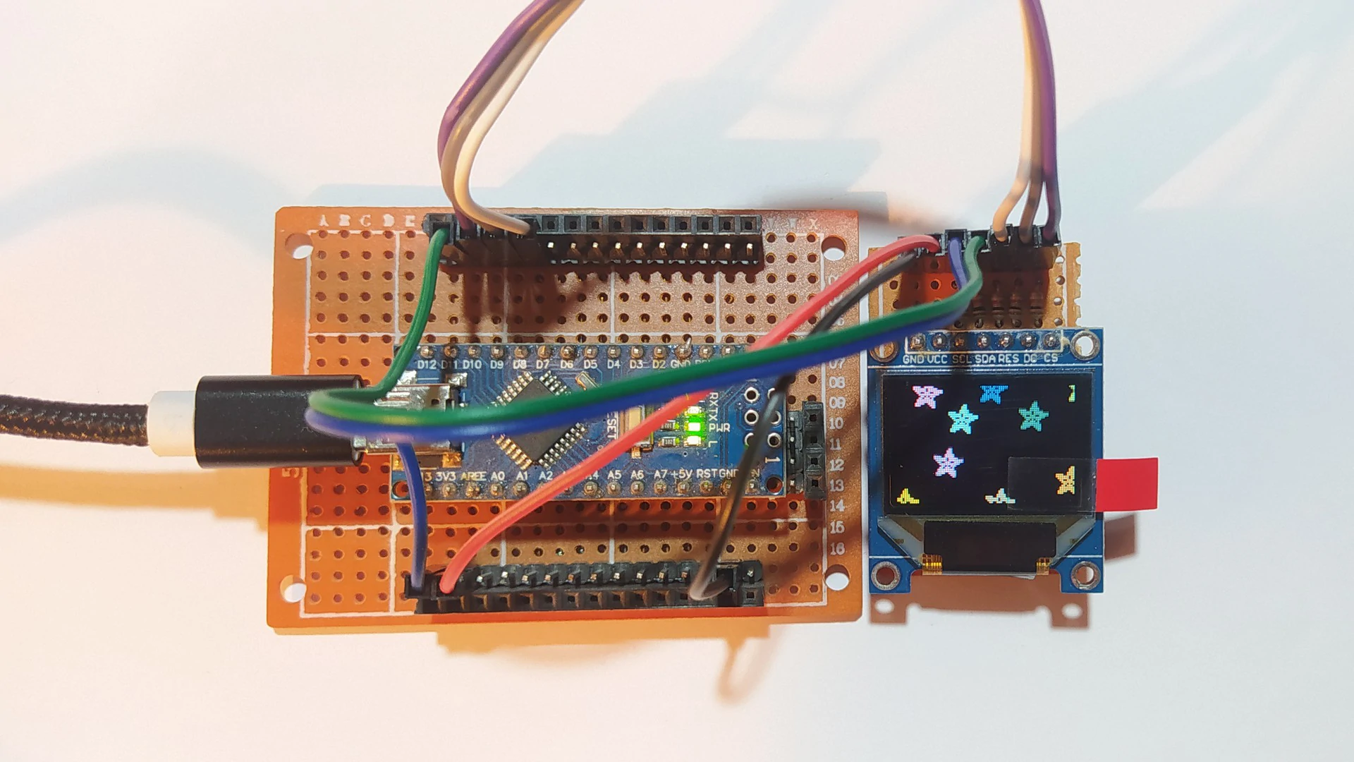
The following video shows a test hardware circuit of Arduino board with SSD1331 OLED display.
Discover more from Simple Circuit
Subscribe to get the latest posts sent to your email.


