Adding a display to an embedded system can bring several benefits, making the device more user-friendly and functional. Displays can be used for diagnostics by showcasing error messages, system logs, or sensor readings in real-time. This can aid in identifying and resolving issues quickly and efficiently.
This post shows how to easily interface an Arduino board with ST7735 TFT display module, how to print texts, numbers, and draw shapes.
Abbreviations:
TFT: Thin-Film Transistor.
LCD: Liquid Crystal Display.
SPI: Serial Peripheral Interface.
MOSI: Master Out Slave In.
MISO: Master In Slave Out.
SCK: Serial Clock
DIY: Do-It-Yourself
The ST7735 TFT Display Module:
The ST7735 is a driver IC commonly used for small, colorful TFT LCD screens. These displays are popular for hobbyist projects due to their low cost, ease of use, and wide availability. This type of displays can be used in various applications including: potable devices, embedded systems, and consumer electronics.
Here are some key features and specifications of the ST7735 display module:
- Operating Voltage: Usually 3.3V for the logic and backlight, though some modules include a regulator for 5V input.
- Display Size and Resolution: ST7735 displays come in various screen sizes, with the most common being 1.8 inches with a resolution of 128×160 pixels.
- Color Depth: 18-bit (262,144 colors) or 16-bit (65,536 colors).
- Communication Interface: These displays use SPI serial communication protocol to communicate with the master device.
- SD Card slot: Some ST7735 breakout boards include a built-in SD card or microSD card slot. This allows us to store colored bitmaps on the SD card and easily display them on the screen.
The image shows a ST7735 breakout board with integrated component details:

ST7735 Display Pin Configuration:
Typically, the ST7735 display module will have the following pins.
- RST: Display reset pin, active low.
- CS: Chip Select pin, active low.
- D/C: Data/Command pin, select data or command input mode to the display, low for data mode and high for command mode.
- DIN (MOSI): Data In, or Master-Out Slave-In pin, SPI data input to the display.
- CLK: SPI clock input to the display.
- VCC: Power supply pin, 3.3V or 5V.
- BL: Backlight LED pin
- GND: Ground.
The ST7735 display module shown in the above image can be supplied with 3.3V or 5V depending on the status of jumper J1, closing the jumper bypasses the AMS1117 3.3V LDO regulator and the display will be configured to work with 3.3V only.
Interfacing Arduino with ST7735 TFT Display Circuit:
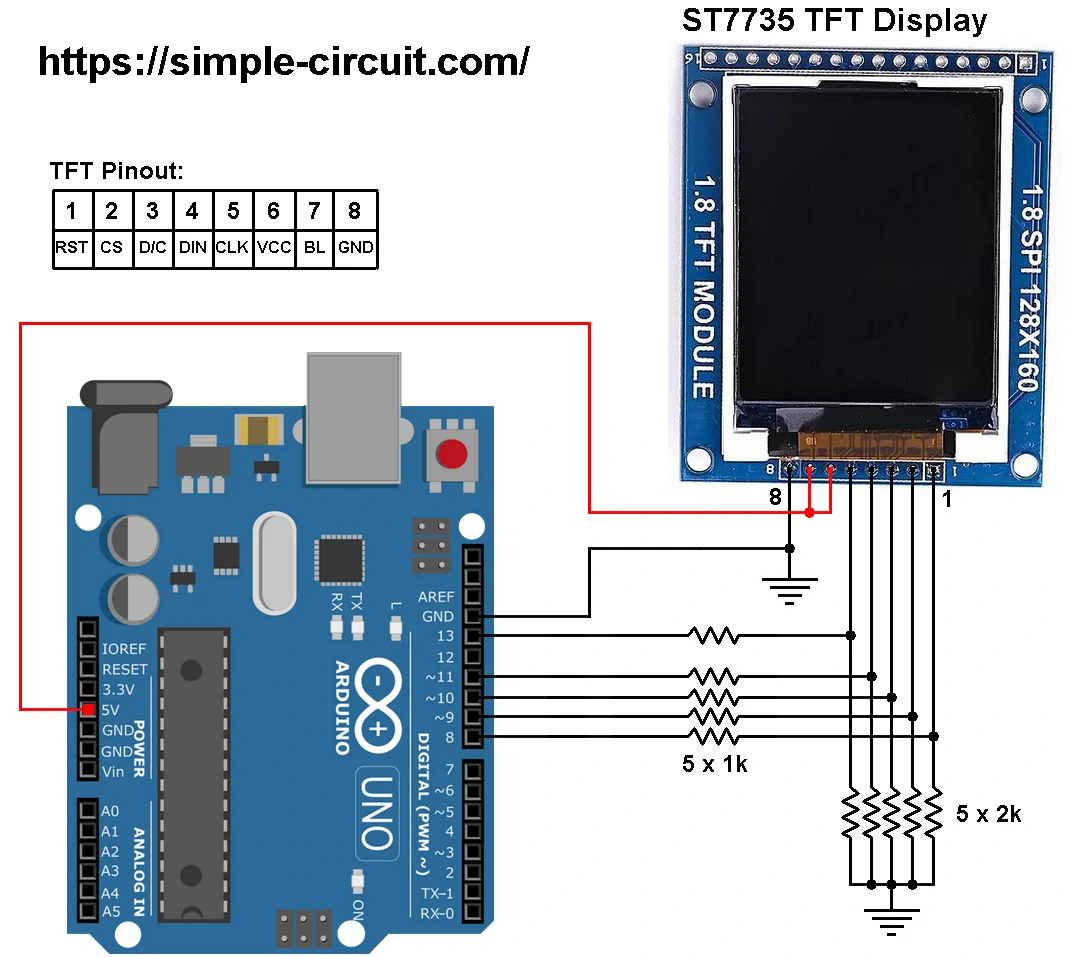
Hardware circuit diagram of the example is shown below.
The ST7735 display module shown in project circuit diagram has 8 pins: (from right to left): RST (reset), CE (chip enable), DC (or D/C: data/command), DIN (data in), CLK (clock), VCC, BL (back light) and GND (ground).
Hardware Required:
Required components are listed below.
- Arduino UNO (or similar) board —> Board details
- ST7735 TFT display module
- 5 x 2k ohm resistor
- 5 x 1k ohm resistor
- Breadboard
- Jumper wires
The ST7735 TFT display controller works with 3.3V only (power supply and control signals). The display module is supplied with 5V that comes from the Arduino board. This module has a built-in 3.3V regulator (AMS1117 3.3) which drops the input 5V into 3.3V.
All Arduino UNO board output pins are 5V, connecting a 5V pin to the ST7735 TFT display may damage its controller chip.
To connect the Arduino to the display module, I used voltage divider for each signal line, this means there are 5 voltage dividers. Each voltage divider consists of a 1k and 2k Ohm resistors, this drops the incoming signal voltage from 5V into 3.3V.
So, the ST7735 TFT display is connected to the Arduino board as follows (each one through voltage divider):
RST pin is connected to Arduino digital pin 8,
CS pin is connected to Arduino digital pin 9,
D/C pin is connected to Arduino digital pin 10,
DIN pin is connected to Arduino digital pin 11,
CLK pin is connected to Arduino digital pin 13.
Other pins are connected as follows:
VCC pin is connected to Arduino 5V pin.
GND pin is connected to Arduino GND pin.
BL (LED) pin is connected to Arduino 5V pin.
Pins 13 and 11 are hardware SPI module pins of the ATmega328P microcontroller, respectively for SCK (serial clock) and MOSI (master-out slave-in).
Interfacing Arduino with ST7735 TFT Display Code:
Project Arduino code is just an example of graphics test provided by Adafruit Industries, with some minor modifications.
To be able to compile project Arduino code, two libraries are required from Adafruit Industries:
The first library is a driver for the ST7735 TFT display which can be installed from Arduino IDE library manager (Sketch —> Include Library —> Manage Libraries…, in the search box write “st7735” and install the one from Adafruit).
The second library is Adafruit graphics library which can be installed also from Arduino IDE library manager.
During installation of the Adafruit ST7735 library, Arduino IDE may ask for installing some other libraries form Adafruit Industries (dependencies).
Project code was tested with the following library versions:
Adafruit GFX Library: Version 1.11.9.
Adafruit ST7735 and ST7789 Library: Version 1.10.4.
Adafruit BusIO: Version 1.16.1.
Programming Hints:
The used libraries are included in the Arduino code as shown below:
1 2 3 | #include <Adafruit_GFX.h> // Include Adafruit Core graphics library #include <Adafruit_ST7735.h> // Include Adafruit Hardware-specific library for ST7735 #include <SPI.h> // Include Arduino SPI library |
The connection between the Arduino UNO board and the ST7735 TFT display is as shown in the above circuit schematic, it is defined in the Arduino code as shown below:
1 2 3 4 | // Define ST7735 display pin connection #define TFT_RST 8 // Or set to -1 and connect to Arduino RESET pin #define TFT_CS 9 #define TFT_DC 10 |
The initialization of the ST7735 TFT display library with the connections previously defined:
1 2 | // Initialize the ST7735 display library with previously defined connections Adafruit_ST7735 tft = Adafruit_ST7735(TFT_CS, TFT_DC, TFT_RST); |
The ST7735 display must be initialized before any print operation, if the initialization failed then the display will show only black screen. The initialization function of the display is the one below:
1 2 | // Initialize the ST7735 TFT display tft.initR(INITR_BLACKTAB); // Init ST7735S chip, black tab |
For more details about Arduino SPI communication, see the following page:
Arduino & Serial Peripheral Interface (SPI)
Rest of code is described through comments.
Full Arduino code:
Example Arduino code can be browsed through the below GitHub link:
ST7735-Graphics-Test
1 2 3 4 5 6 7 8 9 10 11 12 13 14 15 16 17 18 19 20 21 22 23 24 25 26 27 28 29 30 31 32 33 34 35 36 37 38 39 40 41 42 43 44 45 46 47 48 49 50 51 52 53 54 55 56 57 58 59 60 61 62 63 64 65 66 67 68 69 70 71 72 73 74 75 76 77 78 79 80 81 82 83 84 85 86 87 88 89 90 91 92 93 94 95 96 97 98 99 100 101 102 103 104 105 106 107 108 109 110 111 112 113 114 115 116 117 118 119 120 121 122 123 124 125 126 127 128 129 130 131 132 133 134 135 136 137 138 139 140 141 142 143 144 145 146 147 148 149 150 151 152 153 154 155 156 157 158 159 160 161 162 163 164 165 166 167 168 169 170 171 172 173 174 175 176 177 178 179 180 181 182 183 184 185 186 187 188 189 190 191 192 193 194 195 196 197 198 199 200 201 202 203 204 205 206 207 208 209 210 211 212 213 214 215 216 217 218 219 220 221 222 223 224 225 226 227 228 229 230 231 232 233 234 235 236 237 238 239 240 241 242 243 244 245 246 247 248 249 250 251 252 253 254 255 256 257 258 259 260 261 262 263 264 265 266 267 268 269 270 271 272 273 274 275 276 277 278 279 280 281 282 283 284 285 286 287 288 289 290 291 292 293 294 295 296 297 298 299 300 301 302 303 304 305 306 307 308 309 310 311 312 | /************************************************************************************** * Interfacing Arduino board with ST7735 TFT display (128x160 pixel). * This is a free software with NO WARRANTY. * https://simple-circuit.com/ /**************************************************************************************/ #include <Adafruit_GFX.h> // Include Adafruit Core graphics library #include <Adafruit_ST7735.h> // Include Adafruit Hardware-specific library for ST7735 display #include <SPI.h> // Include Arduino SPI library // Define ST7735 display pin connection #define TFT_RST 8 // Or set to -1 and connect to Arduino RESET pin #define TFT_CS 9 #define TFT_DC 10 // Initialize the ST7735 display library with previously defined connections Adafruit_ST7735 tft = Adafruit_ST7735(TFT_CS, TFT_DC, TFT_RST); float p = 3.1415926; void setup(void) { Serial.begin(9600); Serial.print(F("Hello! ST77xx TFT Test")); // Initialize the ST7735 TFT display tft.initR(INITR_BLACKTAB); // Init ST7735S chip, black tab Serial.println(F("Initialized")); uint16_t time = millis(); tft.fillScreen(ST77XX_BLACK); time = millis() - time; Serial.println(time, DEC); delay(500); // large block of text tft.fillScreen(ST77XX_BLACK); testdrawtext("Lorem ipsum dolor sit amet, consectetur adipiscing elit. Curabitur adipiscing ante sed nibh tincidunt feugiat. Maecenas enim massa, fringilla sed malesuada et, malesuada sit amet turpis. Sed porttitor neque ut ante pretium vitae malesuada nunc bibendum. Nullam aliquet ultrices massa eu hendrerit. Ut sed nisi lorem. In vestibulum purus a tortor imperdiet posuere. ", ST77XX_WHITE); delay(1000); // tft print function! tftPrintTest(); delay(4000); // a single pixel tft.drawPixel(tft.width()/2, tft.height()/2, ST77XX_GREEN); delay(500); // line draw test testlines(ST77XX_YELLOW); delay(500); // optimized lines testfastlines(ST77XX_RED, ST77XX_BLUE); delay(500); testdrawrects(ST77XX_GREEN); delay(500); testfillrects(ST77XX_YELLOW, ST77XX_MAGENTA); delay(500); tft.fillScreen(ST77XX_BLACK); testfillcircles(10, ST77XX_BLUE); testdrawcircles(10, ST77XX_WHITE); delay(500); testroundrects(); delay(500); testtriangles(); delay(500); mediabuttons(); delay(500); Serial.println("done"); delay(1000); } void loop() { tft.invertDisplay(true); delay(500); tft.invertDisplay(false); delay(500); } void testlines(uint16_t color) { tft.fillScreen(ST77XX_BLACK); for (int16_t x=0; x < tft.width(); x+=6) { tft.drawLine(0, 0, x, tft.height()-1, color); delay(0); } for (int16_t y=0; y < tft.height(); y+=6) { tft.drawLine(0, 0, tft.width()-1, y, color); delay(0); } tft.fillScreen(ST77XX_BLACK); for (int16_t x=0; x < tft.width(); x+=6) { tft.drawLine(tft.width()-1, 0, x, tft.height()-1, color); delay(0); } for (int16_t y=0; y < tft.height(); y+=6) { tft.drawLine(tft.width()-1, 0, 0, y, color); delay(0); } tft.fillScreen(ST77XX_BLACK); for (int16_t x=0; x < tft.width(); x+=6) { tft.drawLine(0, tft.height()-1, x, 0, color); delay(0); } for (int16_t y=0; y < tft.height(); y+=6) { tft.drawLine(0, tft.height()-1, tft.width()-1, y, color); delay(0); } tft.fillScreen(ST77XX_BLACK); for (int16_t x=0; x < tft.width(); x+=6) { tft.drawLine(tft.width()-1, tft.height()-1, x, 0, color); delay(0); } for (int16_t y=0; y < tft.height(); y+=6) { tft.drawLine(tft.width()-1, tft.height()-1, 0, y, color); delay(0); } } void testdrawtext(char *text, uint16_t color) { tft.setCursor(0, 0); tft.setTextColor(color); tft.setTextWrap(true); tft.print(text); } void testfastlines(uint16_t color1, uint16_t color2) { tft.fillScreen(ST77XX_BLACK); for (int16_t y=0; y < tft.height(); y+=5) { tft.drawFastHLine(0, y, tft.width(), color1); } for (int16_t x=0; x < tft.width(); x+=5) { tft.drawFastVLine(x, 0, tft.height(), color2); } } void testdrawrects(uint16_t color) { tft.fillScreen(ST77XX_BLACK); for (int16_t x=0; x < tft.width(); x+=6) { tft.drawRect(tft.width()/2 -x/2, tft.height()/2 -x/2 , x, x, color); } } void testfillrects(uint16_t color1, uint16_t color2) { tft.fillScreen(ST77XX_BLACK); for (int16_t x=tft.width()-1; x > 6; x-=6) { tft.fillRect(tft.width()/2 -x/2, tft.height()/2 -x/2 , x, x, color1); tft.drawRect(tft.width()/2 -x/2, tft.height()/2 -x/2 , x, x, color2); } } void testfillcircles(uint8_t radius, uint16_t color) { for (int16_t x=radius; x < tft.width(); x+=radius*2) { for (int16_t y=radius; y < tft.height(); y+=radius*2) { tft.fillCircle(x, y, radius, color); } } } void testdrawcircles(uint8_t radius, uint16_t color) { for (int16_t x=0; x < tft.width()+radius; x+=radius*2) { for (int16_t y=0; y < tft.height()+radius; y+=radius*2) { tft.drawCircle(x, y, radius, color); } } } void testtriangles() { tft.fillScreen(ST77XX_BLACK); uint16_t color = 0xF800; int t; int w = tft.width()/2; int x = tft.height()-1; int y = 0; int z = tft.width(); for(t = 0 ; t <= 15; t++) { tft.drawTriangle(w, y, y, x, z, x, color); x-=4; y+=4; z-=4; color+=100; } } void testroundrects() { tft.fillScreen(ST77XX_BLACK); uint16_t color = 100; int i; int t; for(t = 0 ; t <= 4; t+=1) { int x = 0; int y = 0; int w = tft.width()-2; int h = tft.height()-2; for(i = 0 ; i <= 16; i+=1) { tft.drawRoundRect(x, y, w, h, 5, color); x+=2; y+=3; w-=4; h-=6; color+=1100; } color+=100; } } void tftPrintTest() { tft.setTextWrap(false); tft.fillScreen(ST77XX_BLACK); tft.setCursor(0, 30); tft.setTextColor(ST77XX_RED); tft.setTextSize(1); tft.println("Hello World!"); tft.setTextColor(ST77XX_YELLOW); tft.setTextSize(2); tft.println("Hello World!"); tft.setTextColor(ST77XX_GREEN); tft.setTextSize(3); tft.println("Hello World!"); tft.setTextColor(ST77XX_BLUE); tft.setTextSize(4); tft.print(1234.567); delay(1500); tft.setCursor(0, 0); tft.fillScreen(ST77XX_BLACK); tft.setTextColor(ST77XX_WHITE); tft.setTextSize(0); tft.println("Hello World!"); tft.setTextSize(1); tft.setTextColor(ST77XX_GREEN); tft.print(p, 6); tft.println(" Want pi?"); tft.println(" "); tft.print(8675309, HEX); // print 8,675,309 out in HEX! tft.println(" Print HEX!"); tft.println(" "); tft.setTextColor(ST77XX_WHITE); tft.println("Sketch has been"); tft.println("running for: "); tft.setTextColor(ST77XX_MAGENTA); tft.print(millis() / 1000); tft.setTextColor(ST77XX_WHITE); tft.print(" seconds."); } void mediabuttons() { // play tft.fillScreen(ST77XX_BLACK); tft.fillRoundRect(25, 10, 78, 60, 8, ST77XX_WHITE); tft.fillTriangle(42, 20, 42, 60, 90, 40, ST77XX_RED); delay(500); // pause tft.fillRoundRect(25, 90, 78, 60, 8, ST77XX_WHITE); tft.fillRoundRect(39, 98, 20, 45, 5, ST77XX_GREEN); tft.fillRoundRect(69, 98, 20, 45, 5, ST77XX_GREEN); delay(500); // play color tft.fillTriangle(42, 20, 42, 60, 90, 40, ST77XX_BLUE); delay(50); // pause color tft.fillRoundRect(39, 98, 20, 45, 5, ST77XX_RED); tft.fillRoundRect(69, 98, 20, 45, 5, ST77XX_RED); // play color tft.fillTriangle(42, 20, 42, 60, 90, 40, ST77XX_GREEN); } /************************************************************************** This is a library for several Adafruit displays based on ST77* drivers. Works with the Adafruit 1.8" TFT Breakout w/SD card ----> http://www.adafruit.com/products/358 The 1.8" TFT shield ----> https://www.adafruit.com/product/802 The 1.44" TFT breakout ----> https://www.adafruit.com/product/2088 The 1.14" TFT breakout ----> https://www.adafruit.com/product/4383 The 1.3" TFT breakout ----> https://www.adafruit.com/product/4313 The 1.54" TFT breakout ----> https://www.adafruit.com/product/3787 The 1.69" TFT breakout ----> https://www.adafruit.com/product/5206 The 2.0" TFT breakout ----> https://www.adafruit.com/product/4311 as well as Adafruit raw 1.8" TFT display ----> http://www.adafruit.com/products/618 Check out the links above for our tutorials and wiring diagrams. These displays use SPI to communicate, 4 or 5 pins are required to interface (RST is optional). Adafruit invests time and resources providing this open source code, please support Adafruit and open-source hardware by purchasing products from Adafruit! Written by Limor Fried/Ladyada for Adafruit Industries. MIT license, all text above must be included in any redistribution **************************************************************************/ |
Interfacing Arduino with ST7735 TFT Display Video:
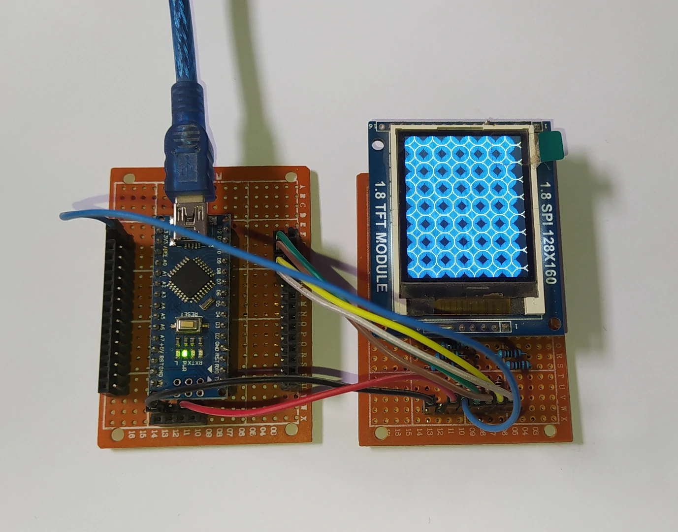
The video below shows my DIY hardware test circuit of an Arduino NANO board with ST7735 TFT display:
Arduino with ST7735 TFT Display Proteus Simulation Video:
The video below shows Proteus simulation of Arduino UNO board with ST7735 TFT display.
Note that Proteus simulation circuit is not the same as real hardware circuit, project hardware circuit diagram is shown above.
Proteus simulation file download link is below, use version 8.15 or higher to open it:
Arduino and ST7735 TFT Proteus simulation
Discover more from Simple Circuit
Subscribe to get the latest posts sent to your email.


