The LM35 temperature sensor is a three pin device (VCC, OUT and GND) with an output voltage linearly related to Centigrade temperature. Since the LM35 output varies with dependent to the temperature we need an ADC (Analog-to-Digital Converter) module to measure this voltage.
This post shows how to build a simple thermometer using PIC12F1822 microcontroller and LM35 analog temperature sensor. Temperature data is displayed on 16×2 LCD screen (I2C LCD). This project works also with DFRobot I2C LCD displays.
The compiler used in this project is Microchip MPLAB XC8 (MPLAB X IDE with MPLAB XC8 compiler).
The LM35 output has linear +10mV/°C scale factor means the following:
If the output voltage = 10mV —> temperature = 1°C
If the output voltage = 100mV —> temperature = 10°C
If the output voltage = 200mV —> temperature = 20°C
If the output voltage = 370mV —> temperature = 37°C
and so on.
LM35 Futures (from datasheet):
- Calibrated Directly in ° Celsius (Centigrade)
- Linear + 10 mV/°C Scale Factor
- 0.5°C Ensured Accuracy (at +25°C)
- Rated for Full −55°C to +150°C Range
- Suitable for Remote Applications
- Low Cost Due to Wafer-Level Trimming
- Operates from 4 to 30 V
- Less than 60-μA Current Drain
- Low Self-Heating, 0.08°C in Still Air
- Nonlinearity Only ±¼°C Typical
- Low Impedance Output, 0.1 Ω for 1 mA Load
The ADC module converts analog data into digital data. The PIC12F1822 MCU has a 10-bit ADC module and a built-in fixed voltage reference (FVR) which makes it a good choice for this application. With the fixed voltage reference we get approximately an exact result. Normally negative and positive references of the ADC module are VSS and VDD respectively, but VDD is not exactly equal to 5.00V and here we should use the fixed voltage reference as a positive reference of the ADC module.
The PIC12F1822 has 3 fixed voltage references: 1.024V, 2.048V and 4.096V. For example if we set the fixed voltage reference to 4.096V and the ADC module is configured so that the negative and the positive references are VSS and FVR (Fixed Voltage Reference) respectively, in this case the equivalent 10-bit digital value of 4.096 is 1023 and 3.00V is 3.00 * 1023/4.096 = 749 , and so on.
In this project I used FVR = 1.024V because the LM35 output is generally less than 1V and also it gave me better result (let’s say higher resolution). Now the ADC module works in the interval between 0 and 1.024V.
Related Projects:
Interfacing I2C LCD with PIC microcontroller | MPLAB Projects
Interfacing PIC12F1822 with 1602 LCD and LM35 sensor | CCS C compiler
Hardware Required:
- PIC12F1822 microcontroller — datasheet
- LM35 temperature sensor — datasheet
- 16×2 LCD screen
- PCF8574 I/O expander (or PCF8574A) — PCF8574 datasheet
- 5 x 10k ohm resistor
- 330 ohm resistor
- 10k ohm variable resistor or potentiometer
- 5V source
- Breadboard
- Jumper wires
Interfacing PIC microcontroller with LM335 sensor circuit:
Project circuit schematic diagram is shown below.
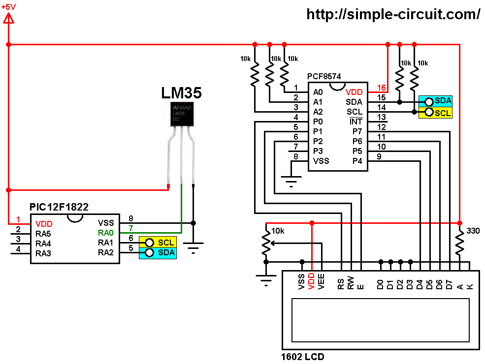
(All grounded terminals are connected together)
The output of the LM35 temperature sensor is connected to analog channel 0 (RA0) of the PIC12F1822 microcontroller.
In this project the PIC12F1822 microcontroller runs with its internal oscillator @ 8 MHz, MCLR pin is configured as an input pin.
Interfacing LM35 sensor with PIC microcontroller C code:
The C code below is for MPLAB XC8 compiler, it was tested with version 2.00 installed on MPLAB X IDE version 5.05.
To be able to compile the C code, a small I2C LCD library for MPLAB XC8 compiler is required which can be downloaded from the following link:
I2C LCD driver for MPLAB XC8 compiler
after the download, add the library file (I2C_LCD.c) to project folder.
The I2C LCD driver file is included with the line:
#include “I2C_LCD.c”
The hardware I2C module of the PIC12F1822 is initialized with a clock frequency of 100KHz (100000Hz):
I2C_Init(100000);
The I2C LCD is initialized with an I2C address of 0x4E:
LCD_Begin(0x4E);
The resolution of PIC12F1822 ADC module is 10-bit and with a positive reference voltage of 1.024V the correspondent digital value is just the input analog voltage in millivolts (mV).
With a scale factor of 10mV/°C the actual temperature is equal to the digital value of the analog input voltage divided by 10.
The microcontroller used in this example is PIC12F1822, configuration words are:
1 2 | #pragma config CONFIG1 = 0x3F84 #pragma config CONFIG2 = 0x1613 |
Where:
- Fail-Safe Clock Monitor enabled
- Internal/External Switchover mode enabled
- CLKOUT function is disabled, I/O function on the CLKOUT pin
- Brown-out Reset (BOR) enabled
- Data memory code protection disabled
- Program memory code protection disabled
- RE3/MCLR pin function is digital input, MCLR internally tied to VDD
- Power-up Timer (PWRT) disabled
- Watchdog Timer (WDT) disabled
- INTOSCIO oscillator: I/O function on CLKIN pin
- Low voltage programming disabled
- In-Circuit Debugger disabled
- Brown-out Reset voltage (Vbor), low trip point selected
- Stack Overflow or Underflow will cause a Reset
- 4xPLL disabled
- Flash Program Memory Self Write disabled
MPLAB XC8 code:
1 2 3 4 5 6 7 8 9 10 11 12 13 14 15 16 17 18 19 20 21 22 23 24 25 26 27 28 29 30 31 32 33 34 35 36 37 38 39 40 41 42 43 44 45 46 47 48 49 50 51 52 53 54 55 56 57 58 59 60 61 62 63 64 65 66 67 68 | /* * Interfacing PIC12F1822 microcontroller with LM35 analog temperature sensor. * Temperature is displayed on 1602 LCD screen (I2C LCD). * C Code for MPLAB XC8 compiler. * Internal oscillator used @ 8MHz. * This is a free software with NO WARRANTY. * http://simple-circuit.com/ */ // set configuration words #pragma config CONFIG1 = 0x3F84 #pragma config CONFIG2 = 0x1613 #include <xc.h> #define _XTAL_FREQ 8000000 #include <stdint.h> // include stdint header #include "I2C_LCD.c" // include I2C LCD driver source file char Temp[] = "00.0 C"; // function for reading analog data uint16_t read_adc() { GO_nDONE = 1; // start an A/D conversion cycle while (GO_nDONE == 1) ; // wait for conversion complete return (ADRESH << 8) | ADRESL ; // return converted data } // main function void main(void) { OSCCON = 0x70; // set internal oscillator to 8MHz FVRCON = 0x81; // Configure FVR to supply ADC positive reference with 1.024V ADCON0 = 0x01; // select channel 0 (AN0), enable ADC module ADCON1 = 0xF3; // right justified, ADC clock supplied from a dedicated RC oscillator, // VREF+ is connected to internal Fixed Voltage Reference (FVR) module __delay_ms(1000); // wait 1 second I2C_Init(100000); // initialize I2C bus with clock frequency of 100kHz LCD_Begin(0x4E); // initialize LCD module with I2C address = 0x4E LCD_Goto(3, 1); // move cursor to column 3 row 1 LCD_Print("Temperature:"); Temp[4] = 223; // put degree symbol (°) while(1) { __delay_ms(1000); // wait 1 second uint16_t raw_temp = read_adc(); // read analog voltage from LM35 output // store temperature in array 'Temp' Temp[0] = (raw_temp/100) % 10 + '0'; // store hundreds Temp[1] = (raw_temp/10) % 10 + '0'; // store tens Temp[3] = raw_temp % 10 + '0'; // store ones LCD_Goto(6, 2); // move cursor column 6 row 2 LCD_Print(Temp); // print Temp } } // end of code. |
Discover more from Simple Circuit
Subscribe to get the latest posts sent to your email.