This post shows how to build a real time clock with 2 alarm functions and temperature monitor using PIC16F887 microcontroller and DS3231 RTC IC. Time, date, alarms and temperature are displayed on 20×4 LCD screen. Time, date and alarms are set with 3 push buttons connected to the PIC microcontroller.
The compiler used in this project is Microchip MPLAB XC8 (MPLAB X IDE with MPLAB XC8 compiler).
Related Projects:
Interfacing LCD with PIC microcontroller | MPLAB Projects
Interfacing DS1307/DS3231 RTC with PIC MCU | MPLAB Projects

Hardware Required:
The components required for this project are listed below.
- PIC16F887 microcontroller —> datasheet
- DS3231 board —> DS3231 datasheet
- 20×4 LCD screen
- 3 x pushbutton
- 2 x 330 ohm resistor
- LED
- 10k ohm variable resistor or potentiometer
- 3V coin cell battery
- 5V source
- Breadboard
- Jumper wires
Real time clock with alarm and temperature monitor circuit:
Project circuit diagram is shown in the image below.
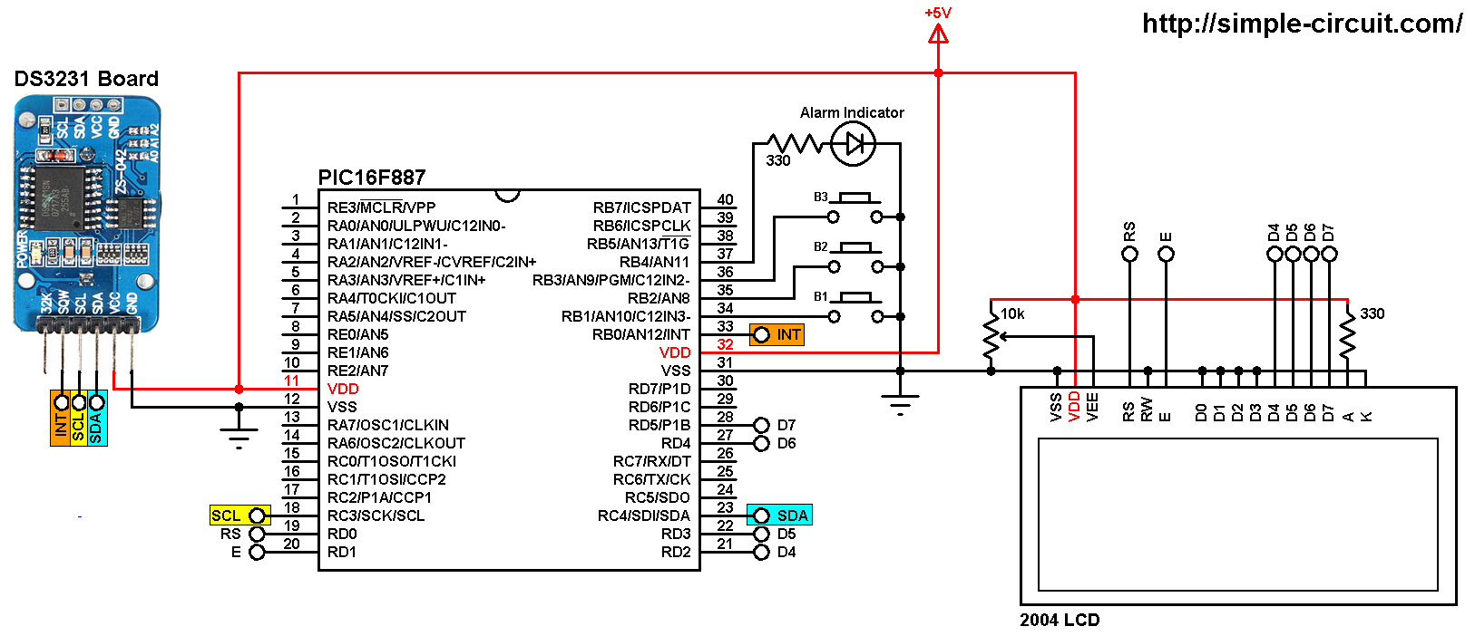
(All grounded terminals are connected together)
The DS3231 board is supplied with 5V as the 2004 LCD and the PIC16F887 microcontroller, there are 3 data lines connected between this board and the microcontroller: SCL line is connected to pin RC3 (#18), SDA line is connected to pin RC4 (#23) and INT line is connected to external interrupt pin RB0 (#33). The DS3231 interrupts the microcontroller when there is an alarm (alarm 1 or alarm 2).
In the circuit there are 3 push buttons: B1, B2 and B3. These buttons are used to set time, date and alarms. Time and date can be adjusted with B1 and B2, button B1 selects time or date parameter (time parameters: hours and minutes; date parameters: day of the week, date, month and year) and B2 increments the selected parameter. Buttons B3 and B2 adjust alarm 1 and alarm 2 parameters (hours, minutes and ON/OFF), button B3 selects the parameter and B2 increments the selected parameter.
Also, there is an LED connected to PIC16F887 pin RB4 (#37), this LED is used as an alarm indicator (alarm 1 and alarm 2), so if there is an alarm, the DS3231 pulls down the INT pin (RB0) which interrupts the microcontroller and the microcontroller turns the LED ON, here button B2 turns both the LED and the occurred alarm OFF.
The 20×4 LCD screen is connected to the PIC16F887 microcontroller as follows:
RS —> RD0 pin
E —> RD1 pin
D4 —> RD2 pin
D5 —> RD3 pin
D6 —> RD4 pin
D7 —> RD5 pin
VSS, RW, D0, D1, D2, D3 and K are connected to circuit GND (ground)
VEE to the variable resistor (or potentiometer) output pin
VDD to +5V and A to +5V through 330 ohm resistor
VEE pin is used to control the contrast of the LCD. A (anode) and K (cathode) are the back light LED pins.
In this project the PIC16F887 microcontroller runs with its internal oscillator @ 8 MHz, MCLR pin is configured as an input pin.
Real time clock with alarm and temperature monitor C code:
The C code below is for MPLAB XC8 compiler, it was tested with version 2.00 installed on MPLAB X IDE version 5.05.
To be able to compile the C code, a small LCD library for MPLAB XC8 compiler is required which can be downloaded from the following link:
MPLAB XC8 LCD Library
after the download, add the library file (LCD_Lib.c) to project folder.
Some programming hints:
The microcontroller turns the LED ON (connected to pin RB4) when it is interrupted by the DS3231, the DS3231 sends the interrupt signal (pulls down the INT line) when there has been an alarm (alarm 1 or alarm 2). Button B2 resets and turns OFF the alarm. If both alarms are active, button B2 will reset and turn OFF the occurred alarm only and keep the other as it is.
To do that we’ve to detect which alarm has been occurred which can be easily done by reading the status register of the DS3231 (A1IF and A2IF flag bits). Turning ON or OFF an alarm is done by writing to the control register (bits: INTCN, A1IE and A2IE). Always INTCN bit should be 1. I used the following line to write 1 to the INTCN bit and to turn OFF the occurred alarm:
I2C_Write(4 | ((!(status_reg & 1)) & alarm1_status) | (((!((status_reg >> 1) & 1)) & alarm2_status) << 1));
alarm1_status and alarm2_status are 1-bit variables (can be 1 or 0), for example if alarm1_status is 1 ==> alarm 1 is ON and if alarm1_status is 0 ==> alarm 1 is OFF. The same thing for alarm 2.
The microcontroller used in this example is PIC16F887, configuration words are:
1 2 | #pragma config CONFIG1 = 0x2CD4 #pragma config CONFIG2 = 0x0700 |
Where:
- In-Circuit Debugger disabled
- Low voltage programming disabled
- Fail-Safe Clock Monitor enabled
- Internal/External Switchover mode enabled
- Brown-out Reset (BOR) disabled
- Data memory code protection disabled
- Program memory code protection disabled
- RE3/MCLR pin function is digital input, MCLR internally tied to VDD
- Power-up Timer (PWRT) disabled
- Watchdog Timer (WDT) disabled
- INTOSCIO oscillator: I/O function on RA6/OSC2/CLKOUT pin, I/O function on RA7/OSC1/CLKIN
- Flash Program Memory Self Write disabled
- Brown-out Reset set to 4.0V
Full MPLAB XC8 code:
1 2 3 4 5 6 7 8 9 10 11 12 13 14 15 16 17 18 19 20 21 22 23 24 25 26 27 28 29 30 31 32 33 34 35 36 37 38 39 40 41 42 43 44 45 46 47 48 49 50 51 52 53 54 55 56 57 58 59 60 61 62 63 64 65 66 67 68 69 70 71 72 73 74 75 76 77 78 79 80 81 82 83 84 85 86 87 88 89 90 91 92 93 94 95 96 97 98 99 100 101 102 103 104 105 106 107 108 109 110 111 112 113 114 115 116 117 118 119 120 121 122 123 124 125 126 127 128 129 130 131 132 133 134 135 136 137 138 139 140 141 142 143 144 145 146 147 148 149 150 151 152 153 154 155 156 157 158 159 160 161 162 163 164 165 166 167 168 169 170 171 172 173 174 175 176 177 178 179 180 181 182 183 184 185 186 187 188 189 190 191 192 193 194 195 196 197 198 199 200 201 202 203 204 205 206 207 208 209 210 211 212 213 214 215 216 217 218 219 220 221 222 223 224 225 226 227 228 229 230 231 232 233 234 235 236 237 238 239 240 241 242 243 244 245 246 247 248 249 250 251 252 253 254 255 256 257 258 259 260 261 262 263 264 265 266 267 268 269 270 271 272 273 274 275 276 277 278 279 280 281 282 283 284 285 286 287 288 289 290 291 292 293 294 295 296 297 298 299 300 301 302 303 304 305 306 307 308 309 310 311 312 313 314 315 316 317 318 319 320 321 322 323 324 325 326 327 328 329 330 331 332 333 334 335 336 337 338 339 340 341 342 343 344 345 346 347 348 349 350 351 352 353 354 355 356 357 358 359 360 361 362 363 364 365 366 367 368 369 370 371 372 373 374 375 376 377 378 379 380 381 382 383 384 385 386 387 388 389 390 391 392 393 394 395 396 397 398 399 400 401 402 403 404 405 406 407 408 409 410 411 412 413 414 415 416 417 418 419 420 421 422 423 424 425 426 427 428 429 430 431 432 433 434 435 436 437 438 439 440 441 442 443 444 445 446 447 448 449 450 451 452 453 454 455 456 457 458 459 460 461 462 463 464 465 466 467 468 469 470 471 472 473 474 475 476 477 478 479 480 481 482 483 484 485 486 487 488 489 490 491 492 493 494 495 496 497 498 499 500 501 502 503 504 505 506 507 508 509 510 511 512 513 514 515 516 517 518 519 520 521 522 523 524 525 526 527 528 529 530 531 532 533 534 535 536 | /* * Real time clock with 2 alarm functions and temperature monitor * using PIC16F887 microcontroller and DS3231 (DS3232). * Time and date are displayed on 1602 LCD screen. * C Code for MPLAB XC8 compiler. * Internal oscillator used @ 8MHz. * This is a free software with NO WARRANTY. * http://simple-circuit.com/ */ // set configuration words #pragma config CONFIG1 = 0x2CD4 #pragma config CONFIG2 = 0x0700 // button definitions #define button1 RB1 // button B1 is connected to RB1 pin #define button2 RB2 // button B2 is connected to RB2 pin #define button3 RB3 // button B2 is connected to RB3 pin #define LED_PIN RB4 // Alarm LED is connected to RB4 pin //LCD module connections #define LCD_RS RD0 #define LCD_EN RD1 #define LCD_D4 RD2 #define LCD_D5 RD3 #define LCD_D6 RD4 #define LCD_D7 RD5 #define LCD_RS_DIR TRISD0 #define LCD_EN_DIR TRISD1 #define LCD_D4_DIR TRISD2 #define LCD_D5_DIR TRISD3 #define LCD_D6_DIR TRISD4 #define LCD_D7_DIR TRISD5 //End LCD module connections #include <xc.h> #define _XTAL_FREQ 8000000 #include <stdint.h> // include stdint header #include "LCD_Lib.c" // include LCD driver source file char Time[] = " : : ", Date[] = " / /20 ", Alarm1[] = "A1: : :00", Alarm2[] = "A2: : :00", Temperature[] = "T: . C"; uint8_t i, second, minute, hour, w_day, m_day, month, year, alarm1_minute, alarm1_hour, alarm2_minute, alarm2_hour, status_reg, alarm1_status, alarm2_status; // external interrupt ISR void __interrupt() EXT(void) { if (INTF){ LED_PIN = 1; INTF = 0; } } /********************** I2C functions **************************/ void I2C_Init(uint32_t i2c_clk_freq) { SSPCON = 0x28; // configure MSSP module to work in I2C mode SSPADD = (_XTAL_FREQ/(4 * i2c_clk_freq)) - 1; // set I2C clock frequency SSPSTAT = 0; } void I2C_Start() { while ((SSPSTAT & 0x04) || (SSPCON2 & 0x1F)); // wait for MSSP module to be free (not busy) SEN = 1; // initiate start condition } void I2C_Repeated_Start() { while ((SSPSTAT & 0x04) || (SSPCON2 & 0x1F)); // wait for MSSP module to be free (not busy) RSEN = 1; // initiate repeated start condition } void I2C_Stop() { while ((SSPSTAT & 0x04) || (SSPCON2 & 0x1F)); // wait for MSSP module to be free (not busy) PEN = 1; // initiate stop condition } void I2C_Write(uint8_t i2c_data) { while ((SSPSTAT & 0x04) || (SSPCON2 & 0x1F)); // wait for MSSP module to be free (not busy) SSPBUF = i2c_data; // update buffer } uint8_t I2C_Read(uint8_t ack) { uint8_t _data; while ((SSPSTAT & 0x04) || (SSPCON2 & 0x1F)); // wait for MSSP module to be free (not busy) RCEN = 1; while ((SSPSTAT & 0x04) || (SSPCON2 & 0x1F)); // wait for MSSP module to be free (not busy) _data = SSPBUF; // read data from buffer while ((SSPSTAT & 0x04) || (SSPCON2 & 0x1F)); // wait for MSSP module to be free (not busy) // send acknowledge pulse ? (depends on ack, if 1 send, otherwise don't send) ACKDT = !ack; ACKEN = 1; return _data; // return data read } /********************** end I2C functions **********************/ // function for button debounce __bit debounce (uint8_t button) { uint8_t count = 0; for(uint8_t i = 0; i < 5; i++) { switch (button) { case 1: if (button1 == 0) count++; break; case 3: if (button3 == 0) count++; break; default: break; } __delay_ms(10); } if(count > 2) return 1; else return 0; } /********************** RTC chip functions *********************/ // convert BCD to decimal function uint8_t bcd_to_decimal(uint8_t number) { return((number >> 4) * 10 + (number & 0x0F)); } // convert decimal to BCD function uint8_t decimal_to_bcd(uint8_t number) { return(((number / 10) << 4) + (number % 10)); } void RTC_read() // read current time & date from RTC chip { I2C_Start(); // start I2C I2C_Write(0xD0); // RTC chip address I2C_Write(0); // send register address I2C_Repeated_Start(); // restart I2C I2C_Write(0xD1); // initialize data read second = I2C_Read(1); // read seconds from register 0 minute = I2C_Read(1); // read minutes from register 1 hour = I2C_Read(1); // read hour from register 2 w_day = I2C_Read(1); // read day of the week from register 3 m_day = I2C_Read(1); // read date from register 4 month = I2C_Read(1); // read month from register 5 year = I2C_Read(0); // read year from register 6 I2C_Stop(); // stop I2C } void alarms_read_display() // read and display alarm1 and alarm2 data function { uint8_t control_reg, temperature_lsb; int8_t temperature_msb; I2C_Start(); // start I2C I2C_Write(0xD0); // RTC chip address I2C_Write(0x08); // send register address (alarm1 minutes register) I2C_Repeated_Start(); // restart I2C I2C_Write(0xD1); // initialize data read alarm1_minute = I2C_Read(1); // read alarm1 minutes alarm1_hour = I2C_Read(1); // read alarm1 hours I2C_Read(1); // skip alarm1 day/date register alarm2_minute = I2C_Read(1); // read alarm2 minutes alarm2_hour = I2C_Read(1); // read alarm2 hours I2C_Read(1); // skip alarm2 day/date register control_reg = I2C_Read(1); // read control register status_reg = I2C_Read(1); // read status register I2C_Read(1); // skip aging offset register temperature_msb = I2C_Read(1); // read temperature MSB temperature_lsb = I2C_Read(0); // read temperature LSB I2C_Stop(); // stop I2C // convert BCD to decimal alarm1_minute = bcd_to_decimal(alarm1_minute); alarm1_hour = bcd_to_decimal(alarm1_hour); alarm2_minute = bcd_to_decimal(alarm2_minute); alarm2_hour = bcd_to_decimal(alarm2_hour); // end conversion // update Alarm1 and Alarm2 Alarm1[8] = alarm1_minute % 10 + '0'; Alarm1[7] = alarm1_minute / 10 + '0'; Alarm1[5] = alarm1_hour % 10 + '0'; Alarm1[4] = alarm1_hour / 10 + '0'; Alarm2[8] = alarm2_minute % 10 + '0'; Alarm2[7] = alarm2_minute / 10 + '0'; Alarm2[5] = alarm2_hour % 10 + '0'; Alarm2[4] = alarm2_hour / 10 + '0'; alarm1_status = control_reg & 0x01; // read alarm1 interrupt enable bit (A1IE) from RTC chip control register alarm2_status = (control_reg >> 1) & 0x01; // read alarm2 interrupt enable bit (A2IE) from RTC chip control register if(temperature_msb < 0){ temperature_msb *= -1; Temperature[2] = '-'; } else Temperature[2] = ' '; temperature_lsb >>= 6; Temperature[4] = temperature_msb % 10 + '0'; Temperature[3] = temperature_msb / 10 + '0'; if(temperature_lsb == 0 || temperature_lsb == 2){ Temperature[7] = '0'; if(temperature_lsb == 0) Temperature[6] = '0'; else Temperature[6] = '5'; } if(temperature_lsb == 1 || temperature_lsb == 3){ Temperature[7] = '5'; if(temperature_lsb == 1) Temperature[6] = '2'; else Temperature[6] = '7'; } Temperature[8] = 223; // put degree symbol (°) LCD_Goto(11, 1); LCD_Print(Temperature); // print temperature LCD_Goto(1, 3); LCD_Print(Alarm1); // print Alarm1 if(alarm1_status) { LCD_Goto(18, 3); LCD_Print("ON "); // if A1IE = 1 print 'ON' } else { LCD_Goto(18, 3); LCD_Print("OFF"); // if A1IE = 0 print 'OFF' } LCD_Goto(1, 4); LCD_Print(Alarm2); // print Alarm2 if(alarm2_status){ LCD_Goto(18, 4); LCD_Print("ON "); // if A2IE = 1 print 'ON' } else { LCD_Goto(18, 4); LCD_Print("OFF"); // if A2IE = 0 print 'OFF' } } void w_day_display() // print day of the week { LCD_Goto(1, 2); switch(w_day){ case 1: LCD_Print("Sun"); break; case 2: LCD_Print("Mon"); break; case 3: LCD_Print("Tue"); break; case 4: LCD_Print("Wed"); break; case 5: LCD_Print("Thu"); break; case 6: LCD_Print("Fri"); break; default: LCD_Print("Sat"); } } // display time and date function void RTC_display() { // convert data from BCD format to decimal format second = bcd_to_decimal(second); minute = bcd_to_decimal(minute); hour = bcd_to_decimal(hour); m_day = bcd_to_decimal(m_day); month = bcd_to_decimal(month); year = bcd_to_decimal(year); // end conversion // update time Time[7] = second % 10 + '0'; Time[6] = second / 10 + '0'; Time[4] = minute % 10 + '0'; Time[3] = minute / 10 + '0'; Time[1] = hour % 10 + '0'; Time[0] = hour / 10 + '0'; // update date Date[9] = year % 10 + '0'; Date[8] = year / 10 + '0'; Date[4] = month % 10 + '0'; Date[3] = month / 10 + '0'; Date[1] = m_day % 10 + '0'; Date[0] = m_day / 10 + '0'; LCD_Goto(1, 1); // go to column 1, row 1 LCD_Print(Time); // print time LCD_Goto(5, 2); // go to column 1, row 2 LCD_Print(Date); // print date w_day_display(); // print day of the week } // make editing parameter blinks function void blink() { uint8_t j = 0; while( j < 100 && (button1 || i >= 5) && button2 && (button3 || i < 5) ) { j++; __delay_ms(5); } } // edit time and date function uint8_t edit(uint8_t x, uint8_t y, uint8_t parameter) { while(debounce(1) || debounce(3)); // call debounce function (wait for B1 & B3 to be released) while(1) { while(!button2) // if button B2 is pressed { parameter++; if(((i == 0) || (i == 5)) && parameter > 23) // if hours > 23 ==> hours = 0 parameter = 0; if(((i == 1) || (i == 6)) && parameter > 59) // if minutes > 59 ==> minutes = 0 parameter = 0; if(i == 2 && parameter > 31) // if date > 31 ==> date = 1 parameter = 1; if(i == 3 && parameter > 12) // if month > 12 ==> month = 1 parameter = 1; if(i == 4 && parameter > 99) // if year > 99 ==> year = 0 parameter = 0; if(i == 7 && parameter > 1) // for alarms ON or OFF (1: alarm ON, 0: alarm OFF) parameter = 0; LCD_Goto(x, y); LCD_PutC(parameter / 10 + '0'); LCD_PutC(parameter % 10 + '0'); if(i >= 5){ RTC_read(); // read data from RTC chip RTC_display(); // display time and date } __delay_ms(200); } LCD_Goto(x, y); LCD_Print(" "); // print 2 spaces blink(); LCD_Goto(x, y); LCD_PutC(parameter / 10 + '0'); LCD_PutC(parameter % 10 + '0'); blink(); if(i >= 5) { RTC_read(); RTC_display(); } if((!button1 && i < 5) || (!button3 && i >= 5)) // if B1 or B3 is pressed { i++; // increment 'i' for the next parameter return parameter; // return parameter value and exit } } } uint8_t on_off(uint8_t x, uint8_t y, uint8_t al) { while(debounce(3)); // call debounce function (wait for B3 to be released) while (1) { while(!button2) // if button B2 is pressed { al = (!al) & 0x01; LCD_Goto(x, y); if(al == 1) LCD_Print("ON "); else LCD_Print("OFF"); __delay_ms(200); } LCD_Goto(x, y); LCD_Print(" "); // print 3 spaces blink(); LCD_Goto(x, y); if(al == 1) LCD_Print("ON "); else LCD_Print("OFF"); blink(); RTC_read(); RTC_display(); if(!button3) if(debounce(3)) { return al; } } } /********************** end RTC chip functions *****************/ /*************************** main function *********************/ void main(void) { OSCCON = 0x70; // set internal oscillator to 8MHz ANSELH = 0; // configure all PORTB pins as digital PORTB = 0; // PORTB initial state TRISB = 0x0F; // configure RB0 ~ 3 as input pins // enable RB0, RB1, RB2 and RB3 internal pull ups nRBPU = 0; // clear RBPU bit (OPTION_REG.7) WPUB = 0x0F; // WPUB register = 0b00001111 INTF = 0; // clear external interrupt flag bit GIE = 1; // enable global interrupts INTEDG = 0; // set external Interrupt on falling edge INTE = 1; // enable external interrupt __delay_ms(1000); // wait 1 second I2C_Init(100000); // initialize I2C bus with clock frequency of 100kHz LCD_Begin(); // initialize LCD module while(1) { if(!button1) // if button B1 is pressed if(debounce(1)) // call debounce function (make sure if B1 is pressed) { i = 0; hour = edit(1, 1, hour); minute = edit(4, 1, minute); while(debounce(1)); // call debounce function (wait for button B1 to be released) while(1) { while(!button2) // if button RB2 button is pressed { w_day++; // increment day if(w_day > 7) w_day = 1; w_day_display(); __delay_ms(200); } LCD_Goto(1, 2); LCD_Print(" "); // print 3 spaces blink(); // call blink function w_day_display(); blink(); // call blink function if(!button1) // if button B1 is pressed if(debounce(1)) // call debounce function (make sure if B1 is pressed) break; } m_day = edit(5, 2, m_day); month = edit(8, 2, month); year = edit(13, 2, year); while(debounce(1)); // call debounce function (wait for button B1 to be released) // convert decimal to BCD minute = decimal_to_bcd(minute); hour = decimal_to_bcd(hour); m_day = decimal_to_bcd(m_day); month = decimal_to_bcd(month); year = decimal_to_bcd(year); // end conversion // write data to DS3231 RTC I2C_Start(); // start I2C I2C_Write(0xD0); // RTC chip address I2C_Write(0); // send register address I2C_Write(0); // reset seconds and start oscillator I2C_Write(minute); // write minute value to RTC chip I2C_Write(hour); // write hour value to RTC chip I2C_Write(w_day); // write day of the week value to RTC chip I2C_Write(m_day); // write date (day of the month) value to RTC chip I2C_Write(month); // write month value to RTC chip I2C_Write(year); // write year value to RTC chip I2C_Stop(); // stop I2C __delay_ms(200); } if(!button3) // if RB3 button is pressed if(debounce(3)) // call debounce function (make sure if B3 is pressed) { i = 5; alarm1_hour = edit(5, 3, alarm1_hour); alarm1_minute = edit(8, 3, alarm1_minute); alarm1_status = on_off(18, 3, alarm1_status); i = 5; alarm2_hour = edit(5, 4, alarm2_hour); alarm2_minute = edit(8, 4, alarm2_minute); alarm2_status = on_off(18, 4, alarm2_status); while(debounce(3)); // call debounce function (wait for button B3 to be released) // convert decimal to BCD alarm1_minute = decimal_to_bcd(alarm1_minute); alarm1_hour = decimal_to_bcd(alarm1_hour); alarm2_minute = decimal_to_bcd(alarm2_minute); alarm2_hour = decimal_to_bcd(alarm2_hour); // end conversion // write alarms data to DS3231 I2C_Start(); // start I2C I2C_Write(0xD0); // RTC chip address I2C_Write(7); // send register address (alarm1 seconds) I2C_Write(0); // write 0 to alarm1 seconds I2C_Write(alarm1_minute); // write alarm1 minutes I2C_Write(alarm1_hour); // write alarm1 hours I2C_Write(0x80); // alarm1 when hours, minutes, and seconds match I2C_Write(alarm2_minute); // write alarm2 minutes I2C_Write(alarm2_hour); // write alarm2 hours I2C_Write(0x80); // alarm2 when hours and minutes match I2C_Write(4 | alarm1_status | (alarm2_status << 1)); // write data to control register (enable interrupt when alarm) I2C_Write(0); // clear alarm flag bits I2C_Stop(); // stop I2C __delay_ms(200); // wait 200ms } if(!button2 && LED_PIN){ // when button B2 pressed with alarm (Reset and turn OFF the alarm) LED_PIN = 0; // turn OFF alarm indicator I2C_Start(); // start I2C I2C_Write(0xD0); // RTC chip address I2C_Write(0x0E); // send register address (control register) // write data to control register (Turn OFF the occurred alarm and keep the other as it is) I2C_Write(4 | ((!(status_reg & 1)) & alarm1_status) | (((!((status_reg >> 1) & 1)) & alarm2_status) << 1)); I2C_Write(0); // clear alarm flag bits I2C_Stop(); // stop I2C } RTC_read(); // read time and date from RTC chip alarms_read_display(); // read and display alarms RTC_display(); // print time & date __delay_ms(50); // wait 50 ms } } /*************************** end main function ********************************/ |
The video below shows how the project should work in hardware circuit (in this video the microcontroller used is PIC16F877A):
Discover more from Simple Circuit
Subscribe to get the latest posts sent to your email.

I NEED HELP. I DON’T UNDERSTAND WHY I HAVE RESULT 2 ERRORS ALWAYS
” make[2]: Leaving directory ‘C:/Users/slots/Documents/DS3231_DS1307.X’
nbproject/Makefile-default.mk:85: recipe for target ‘.build-conf’ failed
make[1]: Leaving directory ‘C:/Users/slots/Documents/DS3231_DS1307.X’
nbproject/Makefile-impl.mk:39: recipe for target ‘.build-impl’ failed
make[2]: *** [build/default/production/LCD_Lib.p1] Error 1
make[2]: *** Waiting for unfinished jobs….
make[1]: *** [.build-conf] Error 2
make: *** [.build-impl] Error 2
BUILD FAILED (exit value 2, total time: 1s)”
WHILE THE SAME PROJECT WITH CCS WORKS FINE.
THANK YOU
What changes can we make in this code to set desired alarm off period as well (instead of using button for disabling alarm) like we set for ON alarm time.