In this blog there are some topics talking about the DHT11 relative humidity and temperature sensor and how to interface it with different types of PIC microcontrollers. The datasheet of the DHT11 sensor shows its characteristics and how it works.
Also the following topic shows the DHT11 timing and how to simulate it using Proteus:
Interfacing PIC16F877A with DHT11 (RHT01) sensor Proteus simulation
This topic shows how to interface this sensor with the microcontroller PIC12F1822. This microcontroller has only 8 pins and 6 of them can work as an I/O pins.
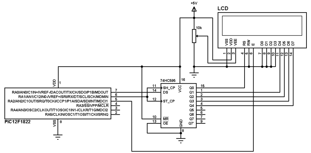
An LCD is used to display temperature and relative humidity values. A shift register is used to make a 3-wire LCD as shown at the following link;
Interfacing PIC12F1822 microcontroller with LCD display – CCS C
Therefor for this simple project we need 3 data lines for the LCD and 1 line for the DHT11 sensor which means we need 4 I/O pins.
Components List:
- PIC12F1822 Microcontroller —> datasheet
- DHT11 (RHT01) Sensor —> datasheet
- 1602 LCD
- 74HC595 Shift Register (74HC164 or CD4094 can do the job)
- 10K Variable Resistor
- 4.7K Resistor
- +5V Power Supply
- Breadboard
- Jumper Wires
- PIC Microcontroller programmer (PICkit 3, PICkit 4…)
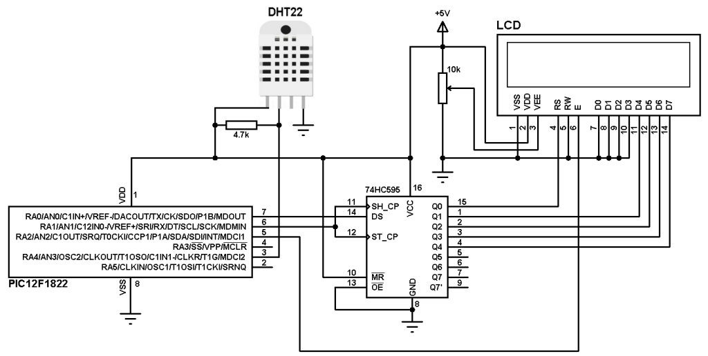
Interfacing PIC12F1822 with DHT11 sensor circuit:
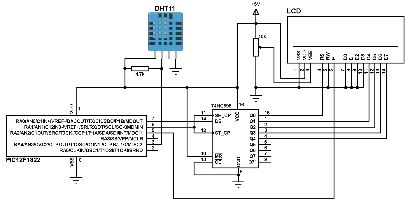
The shift register data line is connected to RA0 pin and the clock line is connected to RA1 pin. LCDs enable pin is connected to pin RA3.
The internal oscillator of the PIC12F1822 microcontroller is used.
To see how to use 74HC164 or CD4094 instead of 74HC595 go to the link above.
The DHT11 sensor has 4 pins:
VCC : Positive power supply (+5V)
DATA : Sensor data input and output
NC : Not connected terminal
GND : Ground (0V)
A pull-up resistor must be added between the DHT11 data pin and VCC (+5V) pin as shown in the circuit schematic (4.7K ~ 10K).
Interfacing PIC12F1822 with DHT11 sensor CCS C code:
If you want to understand the code please read the DHT11 datasheet.
Variables Time_out and k are used to test reading time to avoid wrong data reception and microcontroller hanging.
The microcontroller runs with its internal oscillator at 32MHz (8MHz + PLL).
1 2 3 4 5 6 7 8 9 10 11 12 13 14 15 16 17 18 19 20 21 22 23 24 25 26 27 28 29 30 31 32 33 34 35 36 37 38 39 40 41 42 43 44 45 46 47 48 49 50 51 52 53 54 55 56 57 58 59 60 61 62 63 64 65 66 67 68 69 70 71 72 73 74 75 76 77 78 79 80 81 82 83 84 85 86 87 88 89 90 91 92 93 94 95 96 97 98 99 100 101 102 103 104 105 106 107 108 109 110 111 112 113 114 115 116 117 118 | // Interfacing PIC12F1822 with DHT11 sensor CCS C code // 3-Wire LCD driver must be added //LCD module connections #define LCD_DATA_PIN PIN_A0 #define LCD_CLOCK_PIN PIN_A1 #define LCD_EN_PIN PIN_A2 //End LCD module connections #include <12F1822.h> #fuses NOMCLR INTRC_IO PLL_SW #use delay(clock=32000000) #include <3WireLCD.c> #use fast_io(A) #define DHT11_PIN PIN_A4 // Connection pin between DHT11 and mcu char message1[] = "Temp = 00.0 C "; char message2[] = "RH = 00.0 % "; short Time_out; unsigned int8 T_byte1, T_byte2, RH_byte1, RH_byte2, CheckSum ; void start_signal(){ output_drive(DHT11_PIN); // Configure connection pin as output output_low(DHT11_PIN); // Connection pin output low delay_ms(25); output_high(DHT11_PIN); // Connection pin output high delay_us(30); output_float(DHT11_PIN); // Configure connection pin as input } short check_response(){ delay_us(40); if(!input(DHT11_PIN)){ // Read and test if connection pin is low delay_us(80); if(input(DHT11_PIN)){ // Read and test if connection pin is high delay_us(50); return 1; } } } unsigned int8 Read_Data(){ unsigned int8 i, k, _data = 0; // k is used to count 1 bit reading duration if(Time_out) break; for(i = 0; i < 8; i++){ k = 0; while(!input(DHT11_PIN)){ // Wait until DHT11 pin get raised k++; if(k > 100){ Time_out = 1; break; } delay_us(1); } delay_us(30); if(!input(DHT11_PIN)) bit_clear(_data, (7 - i)); // Clear bit (7 - i) else{ bit_set(_data, (7 - i)); // Set bit (7 - i) while(input(DHT11_PIN)){ // Wait until DHT11 pin goes low k++; if(k > 100){ Time_out = 1; break; } delay_us(1);} } } return _data; } void main() { setup_oscillator(OSC_8MHZ | OSC_PLL_ON); // Set internal oscillator to 32MHz (8MHz and PLL) lcd_initialize(); // Initialize LCD module lcd_cmd(LCD_CLEAR); // LCD Clear delay_ms(1000); while(TRUE){ Time_out = 0; Start_signal(); if(check_response()){ // If there is a response from sensor RH_byte1 = Read_Data(); // read RH byte1 RH_byte2 = Read_Data(); // read RH byte2 T_byte1 = Read_Data(); // read T byte1 T_byte2 = Read_Data(); // read T byte2 Checksum = Read_Data(); // read checksum if(Time_out){ // If reading takes long time lcd_cmd(LCD_CLEAR); // LCD Clear lcd_goto(5, 1); // Go to column 5 row 1 lcd_out("Time out!"); } else{ if(CheckSum == ((RH_Byte1 + RH_Byte2 + T_Byte1 + T_Byte2) & 0xFF)){ message1[7] = T_Byte1/10 + 48; message1[8] = T_Byte1%10 + 48; message1[10] = T_Byte2/10 + 48; message2[7] = RH_Byte1/10 + 48; message2[8] = RH_Byte1%10 + 48; message2[10] = RH_Byte2/10 + 48; message1[11] = 223; // Degree symbol lcd_goto(1, 1); // Go to column 1 row 1 printf(lcd_out, message1); // Display message1 lcd_goto(1, 2); // Go to column 1 row 2 printf(lcd_out, message2); // Display message2 } else{ lcd_cmd(LCD_CLEAR); // LCD Clear lcd_goto(1, 1); // Go to column 1 row 1 lcd_out("Checksum Error!"); } } } else { lcd_cmd(LCD_CLEAR); // LCD Clear lcd_goto(3, 1); // Go to column 3 row 1 lcd_out("No response"); lcd_goto(1, 2); // Go to column 1 row 2 lcd_out("from the sensor"); } delay_ms(1000); } } |
Interfacing PIC12F1822 with DHT11 sensor video:
Discover more from Simple Circuit
Subscribe to get the latest posts sent to your email.