With the tiny microcontroller PIC12F1822 we can read raw data (sectors) stored in the SD card. The SD card can work in SPI mode which makes our interfacing more better since the PIC12F1822 MCU has a built-in SPI module (MSSP module).
This post shows how to interface the SD card with the PIC12F1822 microcontroller in order to read the raw data stored in it (the SD card).
SD card raw data means that there is no use of system files like FAT16 or FAT32. Serial monitor is used to display the data after reading it and here the UART protocol is used.
the link below shows a small PIC12F1822 MCU UART example:
PIC12F1822 UART example with CCS C compiler
In this project I used the MMC/SD card driver for CCS C compiler which is described in the post at the link below:
MMC/SD Card driver for CCS PIC C compiler
Hardware Required:
- PIC12F1822 microcontroller
- SD Card
- AMS1117 3.3V voltage regulator
- 3 x 3.3K ohm resistor
- 3 x 2.2K ohm resistor
- 10K ohm resistor
- 5 x 10uF polarized capacitor
- 100nF ceramic capacitor
- MAX232 chip
- Female RS232 connector
- 5V Power source
- Breadboard
- Jumper wires
Interfacing SD card with PIC12F1822 MCU circuit:
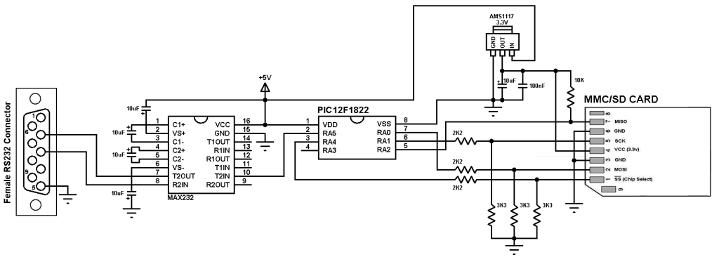
The AMS1117 3.3V voltage regulator is used to supply the SD card with 3.3V. Also 3 voltage dividers are used to step down the 5V which comes from the microcontroller (come from RA0, RA1 and RA4) to about 3V which is sufficient for the SD card. Each voltage divider consists of 2K2 and 3K3 resistors. Pin RA2 of the microcontroller is connected directly to the SD card MISO pin with a pull-up resistor of 10K ohm.
MAX232 integrated circuit is used to interface the microcontroller with the PC, I connected just one wire (RA5) because I need to transmit data from the SD card to the microcontroller and then from the microcontroller to the PC, there is no need to connect the second wire because I don’t need to send data from the PC to the microcontroller.
Hardware SPI module is used by the microcontroller to read data from the SD card, the SPI pins of the PIC12F1822 MCU are:
- SD0 (RA0): connected to pin MOSI of the SD card
- SCK (RA1): connected to pin SCK of the SD card
- SDI (RA2): connected to pin MISO of the SD card
and there is an other pin which is CS (Chip Select) can be connected to any digital output pin (defined in the code), this pin is connected to SS pin of the SD card.
In this project PIC12F1822 MCU uses its internal oscillator and MCLR pin function is disabled.
SD Card raw data read using PIC16F887 CCS C code:
The C code below was tested with CCS PIC C compiler version 5.051.
There are two functions in the code: sdcard_read_byte and sdcard_read_data. I used the first function to read byte with address 0 and I used the second function to read sector number 0. Since the PIC12F1822 has only 128 bytes of RAM, I can not upload all the sector data (512 bytes) in one time, I divided the sector into 16 32-byte parts, so 16 x 32 = 512. The sdcard_read_data function allows us to read data from the SD card starting from any address with any size we want.
The functions sdcard_init , sdcard_read_byte and sdcard_read_data return 0 if OK and non-zero if an error has been occurred.
Complete C code is below.
1 2 3 4 5 6 7 8 9 10 11 12 13 14 15 16 17 18 19 20 21 22 23 24 25 26 27 28 29 30 31 32 33 34 35 36 37 38 39 40 41 42 43 44 45 46 47 48 49 50 51 52 53 | /* Interfacing PIC12F1822 MCU with SD card CCS C code. This example shows raw data read of the SD card. This example does not use any file system (FAT16, FAT32 ...). MMC/SD card driver for CCS C compiler must be installed! */ // SD Card module connections #define SDCARD_SPI_HW // Hardware SPI module is used for the SD card #define SDCARD_PIN_SELECT PIN_A4 // SD card chip select pin is connected to pin RD3 // End SD card module connections #include <12F1822.h> #fuses NOMCLR INTRC_IO PLL_SW #use delay(clock=32000000) #use fast_io(A) #use rs232(xmit = PIN_A5, rcv = PIN_A3, baud = 9600) #include <sdcard.c> // SD card diver source file int8 i, j, one_byte, _data[32], size = 32; void main() { set_tris_a(4); setup_oscillator(OSC_8MHZ | OSC_PLL_ON); // Set internal oscillator to 8MHz with PLL enabled (32MHz) delay_ms(2000); printf("\r"); // Set cursor to first position printf("*** Interfacing PIC12F1822 MCU with SD card ***"); printf("\n\r"); // Start new line printf("Initializing the SD card..."); printf("\n\r"); // Start new line i = sdcard_init(); // Initialize the SD card module if(i == 0){ // If the SD card has been successfully initialized // Read 1 single byte printf("Read byte with address 0:"); printf("\n\r"); // Start new line delay_ms(2000); if(sdcard_read_byte(0, &one_byte) == 0) printf("%X\n\r", one_byte); // Print the value of 'one_byte' in hex format and start new line // Read 1 sector printf("Read sector 0:"); // Sector 0 from address 0 to 511 (512 bytes) printf("\n\r"); // Start new line delay_ms(2000); for( i = 0; i < 16; i++){ if(sdcard_read_data((int32)i * size, size, _data) == 0){ for(j = 0; j < 32; j++) printf("%X", _data[j]); // Print 32 byte of data in hex format } } } // End printf("\n\r"); // Start new line printf("*** END ***"); while(TRUE) ; // Endless loop } |
Finally I got the result shown in the following image:

Discover more from Simple Circuit
Subscribe to get the latest posts sent to your email.