This post shows how to interface PIC12F1822 microcontroller with ST7735 SPI TFT display using CCS PIC C compiler.
For this interfacing we need a driver for the TFT display. Driver topic at the following link:
ST7735 SPI TFT Display Driver for CCS PIC C compiler
Or you can just download it directly from the following link:
ST7735 SPI TFT Display Driver
Put the downloaded C file in your project folder.
Required Components:
- PIC12F1822 Microcontroller
- ST7735R (or ST7735S) 1.8″ SPI TFT Display
- 5 x 1K Resistors
- +5V Power Supply Source
- Breadboard
- Jumper Wires
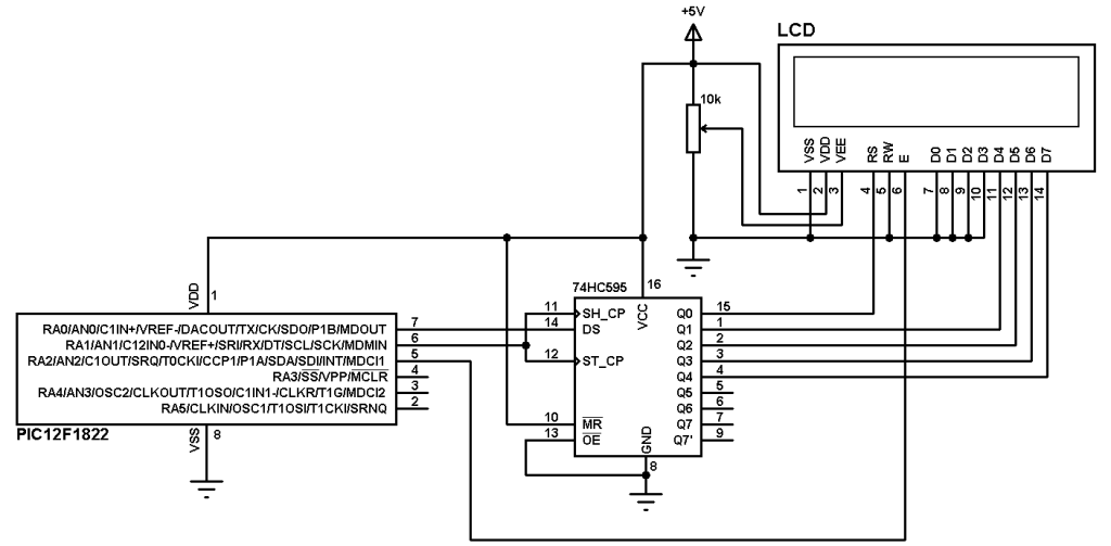
PIC12F1822 and ST7735 SPI TFT Example Circuit:

In this project PIC12F1822 internal oscillator is used and MCLR pin function is disabled.
PIC12F1822 and ST7735 SPI TFT Example CCS C code:
PIC12F1822 Has 1 SPI module, this module is used in this interfacing.
My TFT display is ST7735R Black Tap (ST7735S) and for initializing this type of TFT display I used the following line:
TFT_BlackTab_Initialize();
If you have a TFT display with green or red tabs or a TFT with ST7735B controller read the driver topic above.
Note that green, red and black tabs have the same controller ST7735R.
The following line enables internal oscillator @ 8MHz and also the PLL which makes the microcontroller runs at 32MHz (8MHz x 4).
setup_oscillator(OSC_8MHZ | OSC_PLL_ON);
This code is compiled with CCS PIC C compiler versions 5.051.
1 2 3 4 5 6 7 8 9 10 11 12 13 14 15 16 17 18 19 20 21 22 23 24 25 26 27 28 29 30 31 32 33 34 35 36 | /* PIC12F1822 with ST7735R TFT display example CCS PIC C code ST7735 TFT display driver for CCS PIC C compiler is required coordinates are (x, y) starting from upper left corner (0, 0) */ // TFT module connections #define TFT_CS PIN_A5 #define TFT_DC PIN_A4 #define TFT_SPI_HARDWARE // End TFT module connections #include <12F1822.h> #fuses NOMCLR INTRC_IO PLL_SW #use delay(clock = 32000000) #include <ST7735_TFT.c> #use fast_io(A) unsigned int8 k = 0; char *text = "Hello World!"; void main() { setup_oscillator(OSC_8MHZ | OSC_PLL_ON); // Set internal oscillator to 8MHz with PLL enabled (32MHz) setup_adc_ports(NO_ANALOGS); // Configure all pins as digital TFT_BlackTab_Initialize(); fillScreen(ST7735_BLACK); drawtext(28, 10, text, ST7735_YELLOW, ST7735_BLACK, 1); // Draw text at coordinates (28, 10) with yellow color and black background. Size = 1 strcpy(text, "Hello"); drawtext(19, 30, text, ST7735_RED, ST7735_BLACK, 3); // Draw text at coordinates (19, 30) with red color and black background. Size = 3 strcpy(text, "World!"); drawtext(10, 70, text, ST7735_CYAN, ST7735_BLACK, 3); // Draw text at coordinates (10, 70) with cyan color, black background. Size = 3 while(TRUE){ sprintf(text,"%03u",k); // Place k into text with 3 numbers max and zeroes drawtext(37, 120, text, ST7735_GREEN, ST7735_BLACK, 3); // Draw text at coordinates (37, 120) with green color and black background. Size = 3 delay_ms(500); k++; } } |
Example Video:
Discover more from Simple Circuit
Subscribe to get the latest posts sent to your email.


