We can control DC motor speed and direction using H-bridge circuit, the H-bridge circuit allows us to reverse power supply polarity and with PWM technique we can easily control the speed of the motor. This topic shows how to control the speed and direction of 12V DC motor using PIC16F84A microcontroller and H-bridge circuit.
I want to see how to control DC motor speed using PIC16F84A visit the following topic:
DC motor speed control using PIC16F84A and CCS PIC C
DC Motor speed and direction control with PIC16F84A circuit:
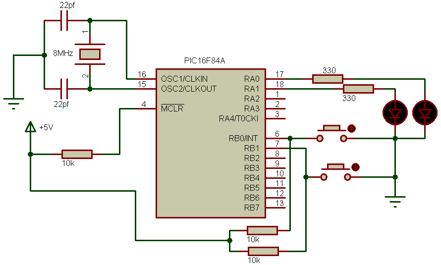
The following circuit schematic shows the full circuit of the project with the H-bridge circuit.
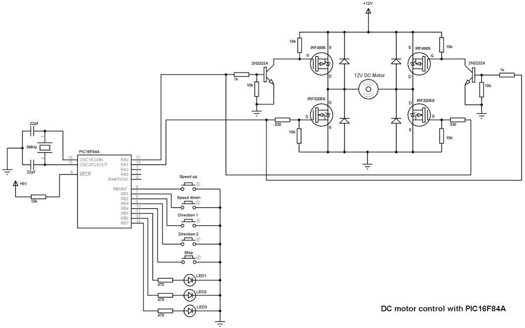
The basic elements of the H-bridge are the four MOSFETs (2 N-type and 2 P-type).
In the circuit there are 5 buttons, the first button which is connected to RB0 pin is used to speed up the motor, and speed down button to decrease motor speed. Third and fourth buttons are used to choose direction rotation of the motor (direction 1 or direction 2). The last button stops the motor no matter what speed or direction.
There are 3 LEDs, LED1 and LED2 are used to indicate motor direction rotation, and the other LED indicates maximum speed which means when it is on the motor runs at maximum speed.
When speed up button is pressed the PWM duty cycle increases which causes the motor to increase its speed and when the duty cycle = 100 LED 3 turned on. In the other hand if speed down button is pressed the duty cycle decreases and the motor speed also decreases.
If the stop button pressed the motor stops and the 3 LEDs turned off.
Software PWM is used with a frequency of 500Hz.
DC Motor speed and direction control with PIC16F84A CCS C code:
The full C code is shown below. Official software PWM library which comes with CCS PIC C compiler is used, this library uses Timer0 to generate the PWM signal.
1 2 3 4 5 6 7 8 9 10 11 12 13 14 15 16 17 18 19 20 21 22 23 24 25 26 27 28 29 30 31 32 33 34 35 36 37 38 39 40 41 42 43 44 45 46 47 48 49 50 51 52 53 54 55 56 57 58 | // DC motor speed and direction control using PIC16F84A CCS C code #include <16F84A.h> #fuses HS,NOWDT,PUT,NOPROTECT #use delay(clock = 8000000) #use fast_io(B) #use fast_io(A) #use pwm(output = pin_a0, output = pin_a1, timer = 0, frequency= 500Hz, duty = 0) unsigned int8 i = 1; void main() { port_b_pullups(TRUE); // Enable PORTB pull-ups output_a(0); // PORTA initial state set_tris_a(0); // All PORTA pins are configured as outputs output_b(0); // PORTB initial state set_tris_b(0x1F); // Configure RB0 to RB4 as inputs pwm_off(); // Turn off all pwm outputs while(TRUE) { if(input(PIN_B0) == 0){ // If RB0 button pressed i++; // Increment i by 1 (i = i + 1) if(i > 99){ i = 100; output_high(PIN_B7);} // RB7 LED ON pwm_set_duty_percent(i * 10UL); // Duty cycle change in tenths % delay_ms(100); } // Wait 100ms if(input(PIN_B1) == 0){ // If RB1 button pressed output_low(PIN_B7); // RB7 LED OFF i--; // Decrement i by 1 (i = i - 1) if(i < 1) i = 1; pwm_set_duty_percent(i * 10UL); // Duty cycle change in tenths % delay_ms(100); } // Wait 100ms if(input(PIN_B2) == 0){ // If RB2 button pressed if(input(PIN_B5) == 0){ output_low(PIN_B6); // RB6 LED OFF pwm_off(); // Turn off pwm for both outputs output_a(0); // PORTA pins low delay_ms(100); // Wait 100ms pwm_on(PIN_A0); // Turn pwm on at RA0 output_high(PIN_B5); // RB5 LED ON if(i > 99) output_high(PIN_B7);}} if(input(PIN_B3) == 0){ // If RB3 button pressed if(input(PIN_B6) == 0){ output_low(PIN_B5); // RB5 LED OFF pwm_off(); // Turn off pwm for both outputs output_a(0); // PORTA pins low delay_ms(100); // Wait 100ms pwm_on(PIN_A1); // Turn PWM on at RA1 output_high(PIN_B6); if(i > 99) output_high(PIN_B7);}} if(input(PIN_B4) == 0){ // If RB4 button pressed pwm_off(); // Turn off pwm for both outputs output_a(0); // PORTA pins low output_b(0);} // PORTB pins low } } |
DC Motor speed and direction control with PIC16F84A video:
The following video shows more about this project with hardware circuit.
Discover more from Simple Circuit
Subscribe to get the latest posts sent to your email.