This topic shows how to interface PIC16F84A microcontroller with DHT22 sensor with hardware circuit.
Related topic:
The following topic shows PIC16F84A microcontroller and DHT22 Proteus simulation and some details about this sensor.
PIC16F84A + DHT22(AM2302, RHT03) sensor Proteus simulation
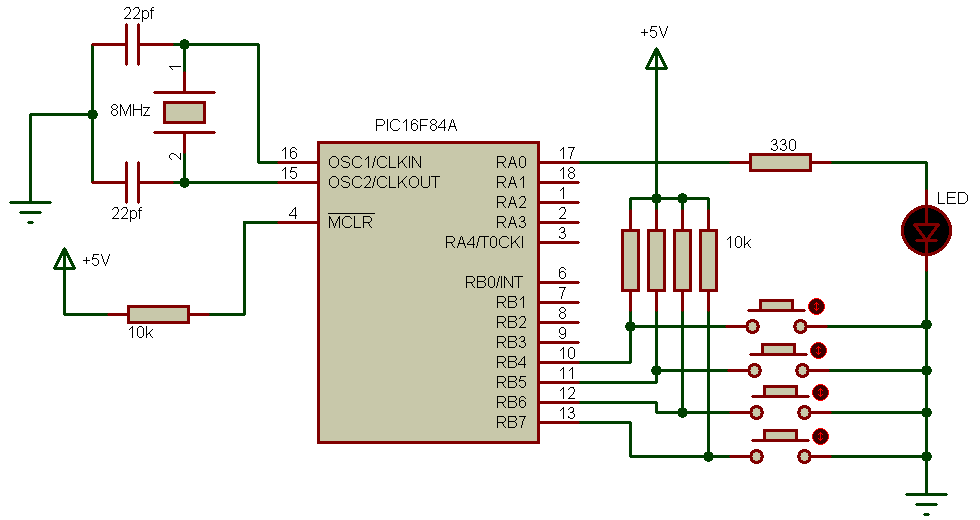
Interfacing PIC16F84A with DHT22 circuit:
The following image shows project circuit schematic.
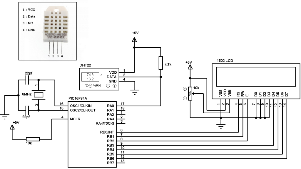
The PIC16F84A needs 5V supply between VDD and VSS.
Interfacing PIC16F84A with DHT22 (AM2302-RHT03) humidity and temperature sensor CCS PIC C compiler code:
The interfacing code was tested with CCS C compiler version 5.051.
If you want to understand the code please read the DHT22 datasheet.
Variables Time_out and k are used to test reading time to avoid wrong data reception or microcontroller hanging.
1 2 3 4 5 6 7 8 9 10 11 12 13 14 15 16 17 18 19 20 21 22 23 24 25 26 27 28 29 30 31 32 33 34 35 36 37 38 39 40 41 42 43 44 45 46 47 48 49 50 51 52 53 54 55 56 57 58 59 60 61 62 63 64 65 66 67 68 69 70 71 72 73 74 75 76 77 78 79 80 81 82 83 84 85 86 87 88 89 90 91 92 93 94 95 96 97 98 99 100 101 102 103 104 105 106 107 108 109 110 111 112 113 114 115 116 117 118 119 | // Interfacing PIC16F84A with DHT22(AM2302 - RHT03) sensor CCS C code //LCD module connections #define LCD_RS_PIN PIN_B0 #define LCD_RW_PIN PIN_B1 #define LCD_ENABLE_PIN PIN_B2 #define LCD_DATA4 PIN_B3 #define LCD_DATA5 PIN_B4 #define LCD_DATA6 PIN_B5 #define LCD_DATA7 PIN_B6 //End LCD module connections #include <16F84A.h> #fuses HS,NOWDT,PUT,NOPROTECT #use delay(clock = 8000000) #include #use fast_io(A) // Connection pin between PIC16F84A and DHT22 sensor #BIT Data_Pin = 0x05.0 // Pin mapped to PORTA.0 #BIT Data_Pin_Direction = 0x85.0 // Pin direction mapped to TRISA.0 char message1[] = "Temp = 00.0 C"; char message2[] = "RH = 00.0 %"; short Time_out ; unsigned int8 T_byte1, T_byte2, RH_byte1, RH_byte2, CheckSum ; unsigned int16 Temp, RH; void start_signal(){ Data_Pin_Direction = 0; // Configure connection pin as output Data_Pin = 0; // Connection pin output low delay_ms(25); Data_Pin = 1; // Connection pin output high delay_us(30); Data_Pin_Direction = 1; // Configure connection pin as input } short check_response(){ delay_us(40); if(!Data_Pin){ // Read and test if connection pin is low delay_us(80); if(Data_Pin){ // Read and test if connection pin is high delay_us(50); return 1;} } } unsigned int8 Read_Data(){ unsigned int8 i, k, _data = 0; // k is used to count 1 bit reading duration if(Time_out) break; for(i = 0; i < 8; i++){ k = 0; while(!Data_Pin){ // Wait until pin goes high k++; if (k > 100) {Time_out = 1; break;} delay_us(1);} delay_us(30); if(!Data_Pin) bit_clear(_data, (7 - i)); // Clear bit (7 - i) else{ bit_set(_data, (7 - i)); // Set bit (7 - i) while(Data_Pin){ // Wait until pin goes low k++; if (k > 100) {Time_out = 1; break;} delay_us(1);} } } return _data; } void main(){ lcd_init(); // Initialize LCD module lcd_putc('f'); // LCD clear while(TRUE){ delay_ms(1000); Time_out = 0; Start_signal(); if(check_response()){ // If there is response from sensor RH_byte1 = Read_Data(); // read RH byte1 RH_byte2 = Read_Data(); // read RH byte2 T_byte1 = Read_Data(); // read T byte1 T_byte2 = Read_Data(); // read T byte2 Checksum = Read_Data(); // read checksum if(Time_out){ // If reading takes long time lcd_putc('f'); // LCD clear lcd_gotoxy(5, 1); // Go to column 5 row 1 lcd_putc("Time out!"); } else{ if(CheckSum == ((RH_Byte1 + RH_Byte2 + T_Byte1 + T_Byte2) & 0xFF)){ RH = RH_byte1; RH = (RH << 8) | RH_byte2; Temp = T_byte1; Temp = (Temp << 8) | T_byte2; if (Temp > 0x8000){ message1[6] = '-'; Temp = Temp & 0x7FFF; } else message1[6] = ' '; message1[7] = (Temp / 100) % 10 + 48; message1[8] = (Temp / 10) % 10 + 48; message1[10] = Temp % 10 + 48; message2[7] = (RH / 100) % 10 + 48; message2[8] = (RH / 10) % 10 + 48; message2[10] = RH % 10 + 48; message1[11] = 223; // Degree symbol lcd_putc('f'); // LCD clear lcd_gotoxy(1, 1); // Go to column 1 row 1 printf(lcd_putc, message1); // Display message1 lcd_gotoxy(1, 2); // Go to column 1 row 2 printf(lcd_putc, message2); // Display message2 } else { lcd_putc('f'); // LCD clear lcd_gotoxy(1, 1); // Go to column 1 row 1 lcd_putc("Checksum Error!"); } } } else { lcd_putc('f'); // LCD clear lcd_gotoxy(3, 1); // Go to column 3 row 1 lcd_putc("No response"); lcd_gotoxy(1, 2); // Go to column 1 row 2 lcd_putc("from the sensor"); } } } |
Interfacing PIC16F84A with DHT22 sensor video:
The following video shows hardware circuit of this project.
Discover more from Simple Circuit
Subscribe to get the latest posts sent to your email.
Hello.
Would it be possible to have the .hex file to inject into the pic?
Thank you.
Bernard.
Bonjour.
Il serait possible d’avoir le fichier .hex à injecter dans le pic ?
Merci.
Bernard.