The RC-5 protocol was developed by Philips in the late 1980s as a semi-proprietary consumer IR (infrared) remote control communication protocol for consumer electronics.
The RC5 has 14 bits per 1 code transmission, the 14 bits can be divided into 4 parts:
The first 2 bits are start bits and they are always logic 1.
The third bit called toggle bit, it can be logic 1 or logic 0.
The next 5 bits are address bits, each device type has its address number for example TV address number is 0, CD player address = 20 …………
And the last 6 bits are command bits, each button has its command number.
For the same device for example TV all the remote control buttons has the same address but each button has its command.
The toggle bit changes whenever a button is pressed.
The RC5 protocol uses Manchester coding, logic 1 and logic 0 are coded as shown in the following drawing where toggle bit is 1, address = 0 and command is 2:

This link from Wikipedia has more details about Philips RC5 protocol.
RC5 IR remote control protocol decoder using PIC16F84A microcontroller:
This topic shows how to decode and get RC5 data of a TV remote control uses RC5 protocol with PIC16F84A microcontroller and CCS PIC C compiler.
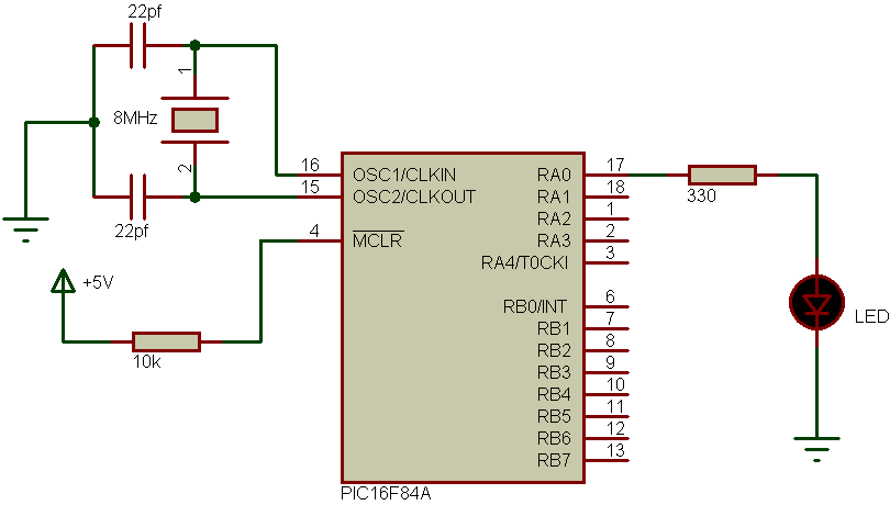
The project circuit schematic is shown below.
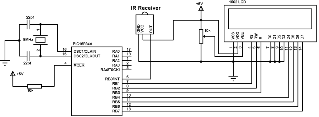
The IR receiver is used to receive the IR signals transmitted from the remote control and convert this signals to a digital data (logic 0, logic 1). The microcontroller PIC16F84A reads digital data from the IR receiver, this data is decoded and the results displayed on 1602 LCD display. The LED which is connected to RB1 pin blinks when RC5 protocol is received.
The PIC16F84A microcontroller needs to be supplied with 5V between pins VDD and VSS.
The following drawing shows how the IR receiver receive and transmit data to the microcontroller:

RC5 IR remote control protocol decoder using PIC16F84A C code:
The code is written and compiled with CCS C compiler.
I made the code simple as I can, no Timer module and no interrupt are used.
The microcontroller waits until the IR receiver receives IR data which means it waits until RB0 pin goes from high to low.
The 2 start bits are used to check if the received IR signal uses RC5 protocol. Each bit is 1778us long. The fist start bit is 1 which means it is 0 for 889us and 1 for 889us, the first 889us is not detected because RB0 not triggered yet and the second 889us is detected using the following code:
while((input(PIN_B0) == 0) && (count < 20)){
count++;
delay_us(50);}
if( (count > 20) || (count < 14))
goto ret;
The signal is checked every 50us and a variable (count) is used to count number of 50s, for example if count = 5 so the total time before RB0 goes high is 250us.
If count >= 20 it means time out and the received signal is high for more than 889us.
If count < 14 it means signal high time is lower than 889us.
The second start bit is checked using the following code:
// Check first 889us
while((input(PIN_B0)) && (count < 20)){
count++;
delay_us(50);}
if( (count > 20) || (count < 14))
goto ret;
// Check 2nd 889us
count = 0;
while((input(PIN_B0) == 0) && (count < 40)){
count++;
delay_us(50);}
if( (count > 40) || (count < 14)) // Signal doesn’t use RC5 protocol
goto ret;
if(count > 30)
delay_us(400);
else
delay_us(1300);
Second bit checking is the same as the first bit checking except that both low 889us are checked.
After the 2nd start bit there is toggle bit which is 1 or 0, and if toggle bit is 0 time required for RB0 pin is 1778us which means to start reading bits we have to add a delay about 400us, and if the toggle bit is 1 we have to wait 1200us.
The following drawing shows the 2 start bit with toggle bit when it’s 0 and when it’s 1:

And the following drawing shows when the microcontroller reads the RC5 bits:

The complete RC5 decoder CCS C code is as the following below.
1 2 3 4 5 6 7 8 9 10 11 12 13 14 15 16 17 18 19 20 21 22 23 24 25 26 27 28 29 30 31 32 33 34 35 36 37 38 39 40 41 42 43 44 45 46 47 48 49 50 51 52 53 54 55 56 57 58 59 60 61 62 63 64 65 66 67 68 69 70 71 72 73 74 75 76 77 78 79 80 81 82 83 84 85 86 87 88 89 90 91 92 93 94 95 96 | // Philips RC5 IR remote control decoder using PIC16F84A CCS C code //LCD module connections #define LCD_RS_PIN PIN_B1 #define LCD_RW_PIN PIN_B2 #define LCD_ENABLE_PIN PIN_B3 #define LCD_DATA4 PIN_B4 #define LCD_DATA5 PIN_B5 #define LCD_DATA6 PIN_B6 #define LCD_DATA7 PIN_B7 //End LCD module connections #include <16F84A.h> #fuses HS,NOWDT,PUT,NOPROTECT #use delay(crystal=8000000) #include <lcd.c> #use fast_io(B) int1 toggle; unsigned int8 count, i, address, command; void main(){ port_b_pullups(TRUE); // Enable PORTB pull-ups output_b(0); // PORTB initial state set_tris_b(1); lcd_init(); // Initialize LCD module lcd_putc('f'); // LCD clear lcd_gotoxy(3, 1); // Go to column 3 row 1 lcd_putc("RC5 protocol"); lcd_gotoxy(5, 2); // Go to column 5 row 2 lcd_putc("decoder"); while(TRUE){ ret: count = 0; while(input(PIN_B0)); // Wait until RB0 pin falls // Check if the received signal uses RC5 protocol while((input(PIN_B0) == 0) && (count < 20)){ count++; delay_us(50);} if( (count > 20) || (count < 14)) // Signal doesn't use RC5 protocol goto ret; // Return count = 0; while((input(PIN_B0)) && (count < 20)){ count++; delay_us(50);} if( (count > 20) || (count < 14)) // Signal doesn't use RC5 protocol goto ret; // Return count = 0; while((input(PIN_B0) == 0) && (count < 40)){ count++; delay_us(50);} if( (count > 40) || (count < 14)) // Signal doesn't use RC5 protocol goto ret; // Return // End check (The received signal uses RC5 protocol) if(count > 30) delay_us(400); else delay_us(1300); for(i = 0; i < 12; i++){ if(i == 0){ if(input(PIN_B0) == 1) toggle = 0; else toggle = 1; } else { if(i < 6){ //Read address bits if(input(PIN_B0) == 1) bit_clear(address, (5 - i)); //Clear bit (5-i) else bit_set(address, (5 - i)); //Set bit (5-i) } else { //Read command bits if(input(PIN_B0) == 1) bit_clear(command, (11 - i)); //Clear bit (11-i) else bit_set(command, (11 - i)); //Set bit (11-i) } } delay_us(1778); } // Display results address &= 0x1F; command &= 0x3F; lcd_putc('f'); lcd_gotoxy(2, 1); lcd_putc("Toggle bit:"); lcd_gotoxy(1, 2); lcd_putc("Adds:"); lcd_gotoxy(9, 2); lcd_putc("Cmd:"); lcd_gotoxy(14, 1); printf(lcd_putc,"%1u",toggle); lcd_gotoxy(6, 2); printf(lcd_putc,"%2u",address); lcd_gotoxy(14, 2); printf(lcd_putc,"%2u",command); } } |
RC5 IR remote control protocol decoder using PIC16F84A video:
The following video shows the project using hardware circuit with some details.
Discover more from Simple Circuit
Subscribe to get the latest posts sent to your email.