This topic shows an easy way to drive a Cd-Rom sensored brushless DC motor (BLDC motor) using PIC16F877A microcontroller with CCS PIC C code.
This motor is three phase motor, it has three stator phases that are excited two at a time to create arotating electric field. This method is fairly easy to implement, but to prevent the permanent magnet rotor from getting locked with the stator, the excitation on the stator must be sequenced in a specific manner while knowing the exact position of the rotor magnets.
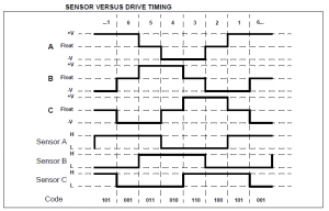
The sensored BLDC motor has 3 hall effect sensors (Sensor A, Sensor B and Sensor C), this sensors sense the rotor position. Each sensor outputs a digital high for 180 electrical degrees and outputs a digital low for the other 180 electrical degrees. The following figure shows the relationship between the sensors outputs and the required motor drive voltages for phases A, B and C.
A three phase bridge is used to energize the BLDC motor windings.
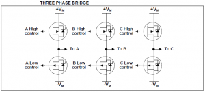
Each phase driver requires 2 pins one for the high side and the other one for the low side which means a total of 6 pins are required to drive the three phase bridge. In this project 6 pins of PORTD will be used.
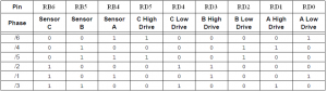
The 3 hall effect sensors needs 3 pins and for that RB4, RB5 and RB6 are used.
A lookup table is used to commutate the motor driver according to the following table:
CD-ROM sensored brushless DC (BLDC) motor speed control with PIC16F877A microcontroller:
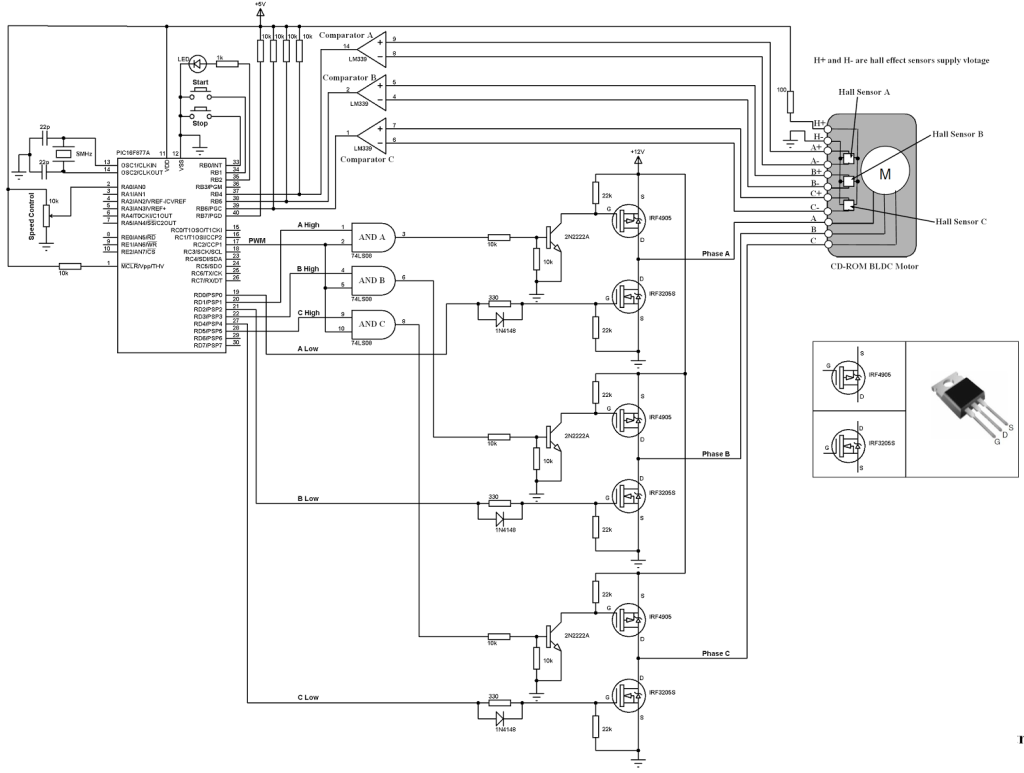
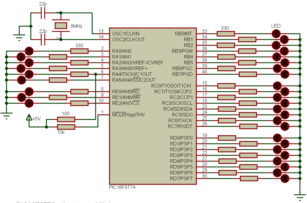
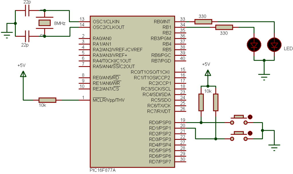
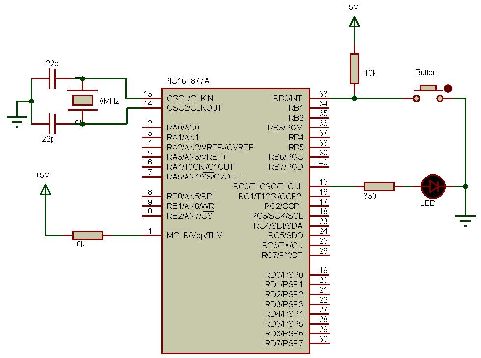
The following image shows project circuit schematic diagram.
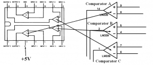
LM339 consists of four independent precision voltage comparators. 3 camparators are needed for the 3 hall effect sensors as shown in the circuit schematic above. A +5V is needed for the LM339 chip as shown below:
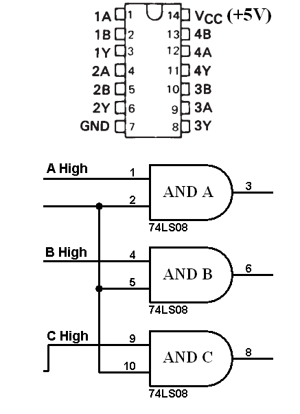
74LS08 contains four independent 2-input AND gates. 3 AND gates are needed to make 3 PWM signals. The 74LS08 must be supplied with +5V as shown below:
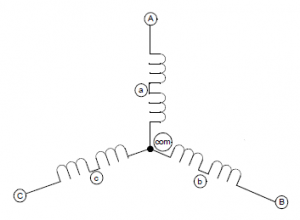
The CD-ROM BLDC motor pin configurations is shown in the following image where the rotor has been removed :
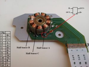
In this BLDC motor each hall effect sensor has 4 pins:
H+ and H- : sensor power supply pins
OUT+ and OUT- : sensor output pins.
For the system power supply there is +5V and +12V. The +12V supplies the 3 phase bridge circuit which is the same as the motor supply voltage.
CD-ROM sensored brushless DC (BLDC) motor control with PIC16F877A microcontroller CCS PIC C compiler code:
This is the full code of this project. The code is small and not complicated.
RB interrupt on change (IOC) is used to interrupt when the rotor changes its position.
A potentiometer connected to analog channel 0 is used to control the BLDC motor speed.
The PWM frequency is 500Hz and the duty cycle is related to analog channel 0 reading.
1 2 3 4 5 6 7 8 9 10 11 12 13 14 15 16 17 18 19 20 21 22 23 24 25 26 27 28 29 30 31 32 33 34 35 36 37 38 39 40 41 42 43 44 45 46 47 48 49 50 51 52 53 54 55 56 57 58 | // CD-ROM Sensored BLDC motor control with PIC16F877A CCS C code #include <16F877A.h> #fuses HS,NOWDT,NOPROTECT,NOLVP #device ADC = 10 #use delay(clock = 8000000) #use fast_io(B) #use fast_io(D) int8 hall; int8 MoveTable[8] = {0, 33, 6, 36, 24, 9, 18, 0}; int16 value; #INT_RB // RB port interrupt on change void rb_isr(void){ hall = (input_b() >> 4) & 7; output_d(MoveTable[hall]); clear_interrupt(INT_RB); } void main(){ output_b(0); // PORTB initial state set_tris_b(0xF3); port_b_pullups(TRUE); // Enable PORTB internal pull-ups output_d(0); set_tris_d(0); setup_adc(ADC_CLOCK_DIV_16); // Set ADC conversion time to 16Tosc setup_adc_ports(AN0); // Configure AN0 as analog set_adc_channel(0); // Select channel 0 input setup_timer_2(T2_DIV_BY_16, 250, 1); // Set PWM frequency to 500Hz setup_ccp1(CCP_OFF); // CCP1 OFF enable_interrupts(GLOBAL); delay_ms(100); // Wait 100ms while(TRUE){ if(!input(PIN_B0)){ // If RB0 button pressed if(input(PIN_B2)){ // Check if motor is already running disable_interrupts(INT_RB); output_d(0); setup_ccp1(CCP_OFF); // CCP1 OFF output_low(PIN_B2); // RB2 LED OFF } } if(!input(PIN_B1)){ // If RB1 button pressed if(!input(PIN_B2)){ // Check if motor is already running output_high(PIN_B2); // RB2 LED ON clear_interrupt(INT_RB); // Clear RB IOC flag bit enable_interrupts(INT_RB); // Enable PORTB IOC setup_ccp1(CCP_PWM); // Configure CCP1 as a PWM hall = (input_b() >> 4) & 7; output_d(MoveTable[hall]); } } if(input(PIN_B2)){ read_adc(ADC_START_ONLY); while(!adc_done()); // Wait until conversion complete value = read_adc(ADC_READ_ONLY); // Read ADC value set_pwm1_duty(value); // Set PWM duty cycle } } } |
CD-ROM BLDC motor control with PIC16F877A microcontroller:
The following video shows a hardware circuit for this project..
References:
Microchip: Sensored BLDC Motor Control Using dsPIC30F2010 (AN957).
Microchip: Brushless DC Motor Control Made Easy (AN857).
Discover more from Simple Circuit
Subscribe to get the latest posts sent to your email.

Thank you for providing such detailed explanation. I’m building a similar project using PIC18F4431. ca you help me with its code in C? thanks.