This post shows how to control 220V AC lamp brightness using PIC16F877A microcontroller and one TRIAC. The TRIAC is a three terminal component (terminal 1, terminal 2 and gate) that is used to control the current following to the load. The TRIAC is fired by applying a pulse to the gate.
Hardware Required:
- PIC16F877A microcontroller
- BT136 TRIAC — datasheet
- 220V AC lamp
- LM393 (or LM339) comparator
- Optocoupler (MOC3020, MOC3021, MOC3022, MOC3023 or equivalent) — datasheet
- 2 x 1N4007 diode (or 1N4001)
- 2 x 220k ohm resistor
- 10k ohm potentiometer
- 2 x 10k ohm resistor
- 470 ohm resistor
- 180 ohm resistor
- 100 ohm resistor
- 0.01µF capacitor
- 5V source
- Breadboard
- Jumper wires
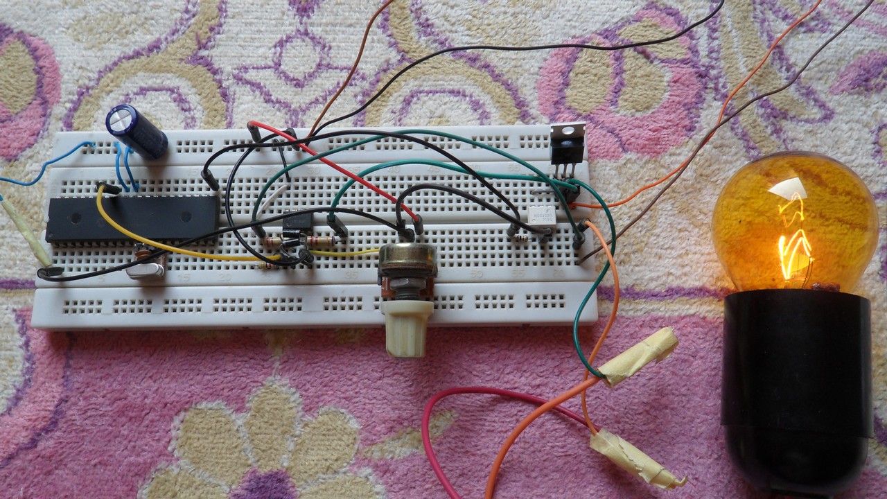
AC Lamp dimmer with PIC16F877A and TRIAC circuit:
The following image shows project circuit schematic diagram.
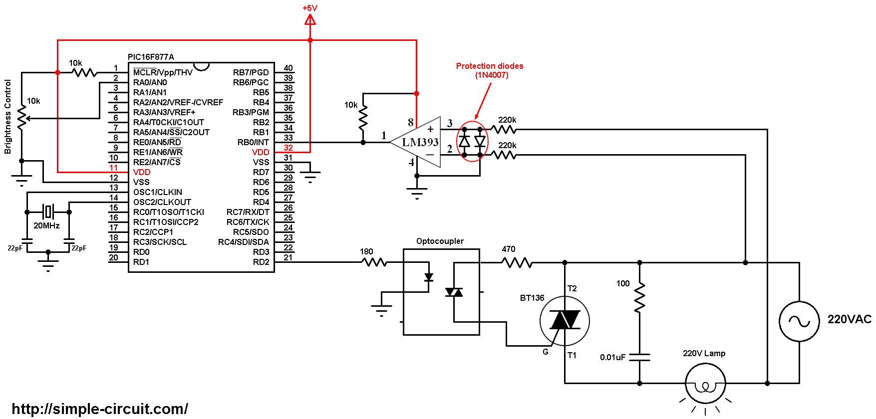
All grounded terminals are connected together.
In this project I used the LM393 (dual comparator IC) for zero crossing detection, the LM339 quad comparator IC also can be used. An optocoupler can be used for the same purpose( zero crossing detection) but I think the comparator is much better. The two diodes which are connected between the non-inverting input (+) and the inverting input (-) of the comparator are used to limit the voltage across the 2 pins. The output of the LM393 (or LM339) is an open collector, so I added a 10k ohm resistor between +5V and comparator output (pull-up resistor).
The output of the analog comparator is connected to RB0 pin of the PI16F877A which is also external interrupt pin of the microcontroller (INT).
The optocoupler (MOC302x) is used for firing the BT136 triac, its LED is connected to PIC16F877A RD2 pin through 180 ohm resistor. I chose the value 180 ohm in order to get a current of about 20mA (current passes through the optocoupler LED).
The 10k potentiometer is used to control the firing angle and therefore the brightness of the lamp.
In this project the PIC16F877A runs with crystal oscillator of 20MHz.
AC Lamp dimmer with PIC16F877A and TRIAC C code:
The C code below is for CCS C compiler, it was tested with version 5.051.
The frequency of my AC source is 50Hz which means the period is 20ms, so the half wave period is 10ms = 10000µs.
The resolution of PIC16F877A microcontroller ADC module is 10 bits which means the digital value can vary between 0 and 1023.
I used PIC16F877A external interrupt (INT) to detect the zero-crossing events, so when there is a zero crossing event (falling or rising), the PIC16F877A interrupted and after some delay (angle alpha) it fires the triac.
1 2 3 4 5 6 7 8 9 10 11 12 13 14 15 16 17 18 19 20 21 22 23 24 25 26 27 28 29 30 31 32 33 34 35 36 37 38 39 40 41 42 43 44 45 46 47 48 49 50 51 52 53 54 55 56 57 58 59 60 61 62 63 64 65 66 67 68 69 70 71 72 73 | /************************************************************************************** AC Lamp light dimmer with PIC16F877A microcontroller C Code for CCS C compiler Crystal oscillator used @ 20MHz This is a free software with NO WARRANTY. http://simple-circuit.com/ ***************************************************************************************/ #define triac_gate PIN_D2 #include <16F877A.h> #device ADC = 10 #fuses HS,NOWDT,NOPROTECT,NOLVP #use delay(clock = 20MHz) #use fast_io(d) #byte OPTION_REG = GETENV("SFR:OPTION_REG") // get OPTION_REG register address #bit INTEDG = OPTION_REG.6 // INTEDG (external interrupt edge) bit address ( OPTION_REG(6) ) int1 ZC = 0; int16 alpha; #INT_EXT // external interrupt ISR void ext_isr(void) { ZC = 1; // toggle external interrupt edge if(INTEDG) INTEDG = 0; else INTEDG = 1; } void main() { output_low(triac_gate); output_drive(triac_gate); setup_adc(ADC_CLOCK_INTERNAL); // set ADC clock source setup_adc_ports(AN0); // configure AN0 pin as analog set_adc_channel(0); // select channel AN0 clear_interrupt(INT_EXT); // clear external interrupt flag bit enable_interrupts(GLOBAL); // enable global interrupts enable_interrupts(INT_EXT); // enable external interrupt delay_ms(500); while(TRUE) { alpha = ( 1023 - read_adc() ) * 10; if (alpha > 9500) alpha = 9500; else if (alpha < 200) alpha = 0; while(ZC == 0) ; // wait for zero crossing event // send firing pulse after alpha delay_us(alpha); output_high(triac_gate); delay_us(200); output_low(triac_gate); ZC = 0; } } // End of code |
AC Lamp dimmer with PIC16F877A and TRIAC video:
Discover more from Simple Circuit
Subscribe to get the latest posts sent to your email.

hex ?
HELLO BRO, 2 QUESTIONS?
DO YOU THINK THIS DIMMER CAN BE USED ON A 2550 PIC?
DO YOU THINK I COULD CONTROL A SINGLE PHASE AC MOTOR?
THANK YOU FOR THE CONTRIBUTIONS.
I need to design dimmer ac in 60v ,ac out 60V,dimmer 30-60v,learn remote 433,8 channels,securities
You can do
Please make a soft starter for 100watt ac motor
can i get hitech c code
I get errors [SPICE] TRAN: Timestep too small; timestep = 1.25e-019: trouble with node #00040.
i set Frequency on AC is 50Hz, is it right ?
This circuit is VERY DANGER AS IT IS CONNECTED WITHOUT ISOLATION to main voltage!!!
If it’s as you say (dangerous), what do you suggest for that ‘isolation’?
You mast isolate using opto-isolator instead of lm393.
Then you’ll get a delay between zero crossing events and falling of the opto-isolator terminal, you can test it using an oscilloscope!
A comparator (such as LM393) gives better results and with the two 220k ohm resistors there’s no dangerous, also the circuit should be well grounded.
please can you convert the program to assembly language or in the syntax mplab compiler?b/se i need the program to compile by mplab,bcoz i have only mplab compiler.
I am a bit nervous about “All grounded terminals are connected together.” It is something i dont like so i desided to put a rectifier bridge with 4n25 optocoupler and a pull up resistor on the collector.
if i do that i have to change the
if(INTEDG) INTEDG = 0;
else INTEDG = 1;
with the follow -> clear_interrupt(int_ext)
and also do i have to add into the main routine -> ext_int_edge(H_to_L)
or it is not necessary?
Yes you can do that but I don’t know if it will give you a good result!
Try with the following:
Remove the 2 lines below:
if(INTEDG) INTEDG = 0;
else INTEDG = 1;
In the main function replace: enable_interrupts(INT_EXT); by: enable_interrupts(INT_EXT_L2H);
Also, doesnt it need in the interrupt service routine the follow clear_interrupt(int_ext)
#INT_EXT
void ext_isr(void)
{
ZC = 1;
clear_interrupt(int_ext)
}
You can remove clear_interrupt(int_ext); because CCS C compiler already do that(clears the interrupt flag) unless you add NOCLEAR after #INT_EXT.
Thanks for the reply Simple Projects. I have a couple of questions. I am new to ccs c compiler so
excuse me if my questions are too simple. I have to say that i do have looked at the manual first but i have been confused. Why do we use the below two commands?
#byte OPTION_REG = GETENV(“SFR:OPTION_REG”)
#bit INTEDG = OPTION_REG.6
Are there for this command? -> if(INTEDG)
if yes, why is that? I mean when we define the chip “#include ” doesnt the compiler already know that?
What exactly does this command? #use fast_io(d)
Thanks
The directive #use fast_io causes the compiler to perform I/O operations without programming of the direction register (see CCS C manual).
INTEDG bit (or OPTION_REG bit number 6) decides the external interrupt edge (more details in PIC16F877A datasheet).
Please make a video on nec remote control light dimmer… I am getting some problem
which is the reason behind output_drive(triac_gate);?
It sets ‘triac_gate’ pin to output.
Pin ‘triac_gate’ is previously defined as PIN_D2.
Esta función establece el pin especificado en modo de salida (TRIS bit 0).