This topic shows how to build a real time clock (RTC) using PIC16F877A microcontroller and a low cost chip which is DS1307.
The DS1307 is an 8-pin integrated circuit uses I2C communication protocol to communicate with master device which is in our case the PIC16F877A microcontroller. This small chip can count seconds, minutes, hours, day, date, month and year with leap-year up to year 2100.
The DS1307 receives and transfers data (clock data and calendar data) as BCD format, so after receiving data we have to convert these data into decimal data, and before writing data to the DS1307 we have to convert this data from decimal to BCD format. For example we have the BCD number 33, converting this number into decimal gives 21.
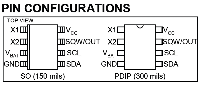
The following image shows the DS1307 pin configurations:

And the following circuit is typical operating circuit for the DS1307 RTC:

A 3V battery can be connected between VBAT and GND which can be used as a backup supply input.
The DS1307 uses an external 32.768KHz crystal and there is no need to add any resistors or capacitors with it.
More information are in the DS1307 RTC datasheet.
Interfacing PIC16F877A with DS1307 RTC:
The following image shows the interfacing circuit schematic diagram.

The circuit is clear and simple. The LCD is used to display the time as well as the date. There are two push buttons to adjust time and date as shown in the video below.
Interfacing PIC16F877A with DS1307 RTC CCS C code:
The following C code is the full code of this project.
PIC16F877A hardware I2C module is used at 100KHz.
1 2 3 4 5 6 7 8 9 10 11 12 13 14 15 16 17 18 19 20 21 22 23 24 25 26 27 28 29 30 31 32 33 34 35 36 37 38 39 40 41 42 43 44 45 46 47 48 49 50 51 52 53 54 55 56 57 58 59 60 61 62 63 64 65 66 67 68 69 70 71 72 73 74 75 76 77 78 79 80 81 82 83 84 85 86 87 88 89 90 91 92 93 94 95 96 97 98 99 100 101 102 103 104 105 106 107 108 109 110 111 112 113 114 115 116 117 118 119 120 121 122 123 124 125 126 127 128 129 130 131 132 133 134 135 136 137 138 139 140 141 142 143 144 145 146 147 148 149 150 151 152 153 154 155 156 157 158 159 160 161 162 163 164 165 166 167 168 169 170 171 172 173 174 175 176 177 178 179 180 181 182 183 184 185 186 | // Interfacing PIC16F877A with DS1307 RTC CCS C code //LCD module connections #define LCD_RS_PIN PIN_B0 #define LCD_RW_PIN PIN_B1 #define LCD_ENABLE_PIN PIN_B2 #define LCD_DATA4 PIN_B3 #define LCD_DATA5 PIN_B4 #define LCD_DATA6 PIN_B5 #define LCD_DATA7 PIN_B6 //End LCD module connections #include <16F877A.h> #fuses HS,NOWDT,NOPROTECT,NOLVP #use delay(clock = 8000000) #include #use fast_io(D) #use I2C(master, I2C1, FAST=100000) char time[] = "TIME: : : "; char calendar[] = "DATE: / /20 "; unsigned int8 second, second10, minute, minute10, hour, hour10, date, date10, month, month10, year, year10, day; void ds1307_display(){ second10 = (second & 0x70) >> 4; second = second & 0x0F; minute10 = (minute & 0x70) >> 4; minute = minute & 0x0F; hour10 = (hour & 0x30) >> 4; hour = hour & 0x0F; date10 = (date & 0x30) >> 4; date = date & 0x0F; month10 = (month & 0x10) >> 4; month = month & 0x0F; year10 = (year & 0xF0) >> 4; year = year & 0x0F; time[12] = second + 48; time[11] = second10 + 48; time[9] = minute + 48; time[8] = minute10 + 48; time[6] = hour + 48; time[5] = hour10 + 48; calendar[14] = year + 48; calendar[13] = year10 + 48; calendar[9] = month + 48; calendar[8] = month10 + 48; calendar[6] = date + 48; calendar[5] = date10 + 48; lcd_gotoxy(1, 1); // Go to column 1 row 1 printf(lcd_putc, time); // Display time lcd_gotoxy(1, 2); // Go to column 1 row 2 printf(lcd_putc, calendar); // Display calendar } void ds1307_write(unsigned int8 address, data_){ i2c_start(); // Start I2C i2c_write(0xD0); // DS1307 address i2c_write(address); // Send register address i2c_write(data_); // Write data to the selected register i2c_stop(); // Stop I2C } void main(){ output_d(0); set_tris_d(6); // Configure RD1 & RD2 as inputs lcd_init(); // Initialize LCD module lcd_putc('f'); // LCD clear ds1307_write(0, 0); //Reset seconds and start oscillator while(TRUE){ if(input(PIN_D1) == 0){ // Convert BCD to decimal minute = minute + minute10 * 10; hour = hour + hour10 * 10; date = date + date10 * 10; month = month + month10 * 10; year = year + year10 * 10; // End conversion lcd_putc('f'); // LCD clear lcd_gotoxy(5, 1); // Go to column 5 row 1 lcd_putc("Minutes:"); delay_ms(200); while(TRUE){ if(input(PIN_D2) == 0) minute++; if(minute > 59) minute = 0; lcd_gotoxy(8, 2); // Go to column 8 row 2 printf(lcd_putc,"%02u", minute); if(input(PIN_D1) == 0) break; delay_ms(200); } lcd_putc('f'); // LCD clear lcd_gotoxy(6, 1); // Go to column 6 row 1 lcd_putc("Hour:"); delay_ms(200); while(TRUE){ if(input(PIN_D2) == 0) hour++; if(hour > 23) hour = 0; lcd_gotoxy(8, 2); // Go to column 8 row 2 printf(lcd_putc,"%02u", hour); if(input(PIN_D1) == 0) break; delay_ms(200); } lcd_putc('f'); // LCD clear lcd_gotoxy(6, 1); // Go to column 6 row 1 lcd_putc("Date:"); delay_ms(200); while(TRUE){ if(input(PIN_D2) == 0) date++; if(date > 31) date = 1; lcd_gotoxy(8, 2); // Go to column 8 row 2 printf(lcd_putc,"%02u", date); if(input(PIN_D1) == 0) break; delay_ms(200); } lcd_putc('f'); // LCD clear lcd_gotoxy(6, 1); // Go to column 6 row 1 lcd_putc("Month:"); delay_ms(200); while(TRUE){ if(input(PIN_D2) == 0) month++; if(month > 12) month = 1; lcd_gotoxy(8, 2); // Go to column 8 row 2 printf(lcd_putc,"%02u", month); if(input(PIN_D1) == 0) break; delay_ms(200); } lcd_putc('f'); // LCD clear lcd_gotoxy(6, 1); // Go to column 6 row 1 lcd_putc("Year:"); lcd_gotoxy(7, 2); // Go to column 7 row 1 lcd_putc("20"); delay_ms(200); while(TRUE){ if(input(PIN_D2) == 0) year++; if(year > 99) year = 0; lcd_gotoxy(9, 2); // Go to column 9 row 2 printf(lcd_putc,"%02u", year); if(input(PIN_D1) == 0){ // Convert decimal to BCD minute = ((minute/10) << 4) + (minute % 10); hour = ((hour/10) << 4) + (hour % 10); date = ((date/10) << 4) + (date % 10); month = ((month/10) << 4) + (month % 10); year = ((year/10) << 4) + (year % 10); // End conversion ds1307_write(1, minute); ds1307_write(2, hour); ds1307_write(4, date); ds1307_write(5, month); ds1307_write(6, year); ds1307_write(0, 0); //Reset seconds and start oscillator delay_ms(200); break; } delay_ms(200); } } i2c_start(); // Start I2C i2c_write(0xD0); // DS1307 address i2c_write(0); // Send register address i2c_start(); // Restart I2C i2c_write(0xD1); // Initialize data read second =i2c_read(1); // Read seconds from register 0 minute =i2c_read(1); // Read minutes from register 1 hour = i2c_read(1); // Read hour from register 2 day = i2c_read(1); // Read day from register 3 date = i2c_read(1); // Read date from register 4 month = i2c_read(1); // Read month from register 5 year = i2c_read(0); // Read year from register 6 i2c_stop(); // Stop I2C ds1307_display(); // Diaplay results delay_ms(50); } } |
Interfacing PIC16F877A with DS1307 RTC video:
The following video shows a hardware circuit of this project with some details about the circuit.
Discover more from Simple Circuit
Subscribe to get the latest posts sent to your email.


