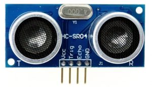
The distance to an obstacle can be measured with the low cost ultrasonic sensor HC-SR04 (HC-SR05). The HC-SR04 sensor can measure distances form 2 to 400cm with an accuracy of 3mm. This sensor module includes ultrasonic transmitter, ultrasonic receiver and control circuit.
The HC-SR04 ultrasonic sensor has 4 pins as shown below where:
VCC – Positive power supply (+5V)
Trig – Trigger input pin
Echo – Echo output pin
GND – Ground (0V)
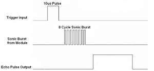
HC-SR04 ultrasonic sensor timing diagram:
The timing diagram of the HC-SR04 ultrasonic sensor is shown below.
First we have to supply the sensor trigger pin with a pulse of 10µs and the sensor will automatically send 8 cycles burst of ultrasound at 40 kHz and raise its echo pin. The Echo is a distance object that is pulse width and the range in proportion. You can calculate the range through the time interval between sending trigger signal and receiving echo signal. Formula: uS / 58 = centimeters or uS / 148 =inch; or:
the range = high level time * velocity (340M/S) / 2.
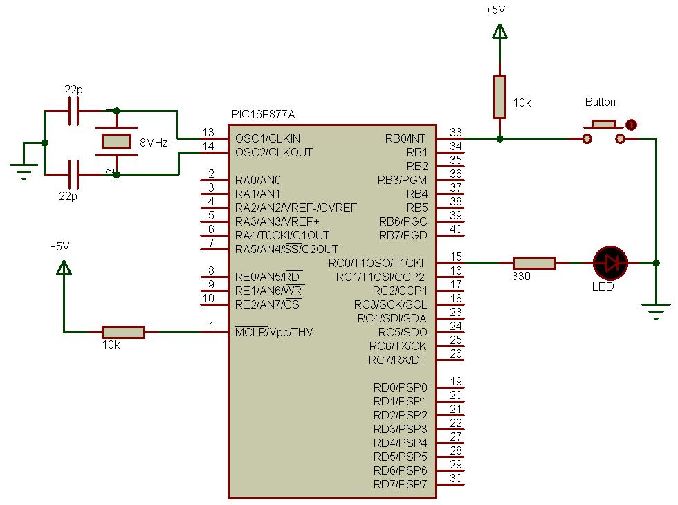
Interfacing PIC16F877A with HC-SR04 ultrasonic sensor circuit:
Project circuit schematic is shown below.
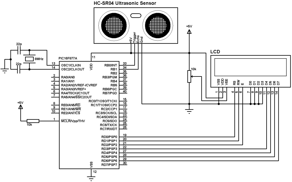
The microcontroller runs with 8MHz crystal oscillator.
HC-SR04 Ultrasonic sensor Trigger pin is connected to RB0 pin and Echo pin is connected to RB1 pin.
Interfacing PIC16F877A with HC-SR04 ultrasonic sensor CCS C code:
Here are some hints about the C code.
The sensor needs at least 10µs pulse at Trigger pin which is done as follows (Trigger pin is connected to RB0 pin:
output_high(PIN_B0);
delay_us(10);
output_low(PIN_B0);
After sending the trigger pulse we have to wait until the module raises its Echo output pin where the Echo pin is connected to pin RB1. If the waiting time is too long that means there is a problem and the code returns error. Timer1 module is used to count elapsed time which is configured to increment by 1 every 1µs (8MHz mcu frequency used).
setup_timer_1 (T1_INTERNAL | T1_DIV_BY_2);
Waiting HC-SR04 module to raise its Echo pin with timeout property code where variable check is used as a return variable (if there is a timeout problem check = 1).
The timeout property is used to prevent the microcontroller from hanging.
while(!input(PIN_B1) && (get_timer1() < 1000));
if(get_timer1() > 990)
check = 1;
If there is no problem the module raises its Echo pin for a certain time, this time is proportional to distance from the sensor the the obstacle. Timer1 is used to count this time as follows:
while(input(PIN_B1) && (i < 25000))
i = get_timer1();
if(i > 24990)
check = 2;
If there is an out of range the code returns error by making the variable check = 2.
For the variable check:
If check = 0: There is no problem
If check = 1: There is a timeout error
If check = 2: There is an out of range error.
Project full code is as below:
1 2 3 4 5 6 7 8 9 10 11 12 13 14 15 16 17 18 19 20 21 22 23 24 25 26 27 28 29 30 31 32 33 34 35 36 37 38 39 40 41 42 43 44 45 46 47 48 49 50 51 52 53 54 55 56 57 58 59 60 61 62 | // Interfacing PIC16F877A with HC-SR04 ultrasonic sensor CCS C code //LCD module connections #define LCD_RS_PIN PIN_D0 #define LCD_RW_PIN PIN_D1 #define LCD_ENABLE_PIN PIN_D2 #define LCD_DATA4 PIN_D3 #define LCD_DATA5 PIN_D4 #define LCD_DATA6 PIN_D5 #define LCD_DATA7 PIN_D6 //End LCD module connections #include <16F877A.h> #fuses HS,NOWDT,NOPROTECT,NOLVP #use delay(clock = 8000000) #include <lcd.c> #use fast_io(B) int8 check; unsigned int16 i, distance; void main(){ output_b(0); set_tris_b(2); // Configure RB1 as input lcd_init(); // Initialize LCD module setup_timer_1 (T1_INTERNAL | T1_DIV_BY_2); // Configure Timer1 module set_timer1(0); // Reset Timer1 lcd_putc('\f'); // LCD Clear lcd_gotoxy(4, 1); // Go to column 4 row 1 lcd_putc("Distance:"); while(TRUE){ check = 0; i = 0; output_high(PIN_B0); delay_us(10); output_low(PIN_B0); set_timer1(0); // Reset Timer1 while(!input(PIN_B1) && (get_timer1() < 1000)); if(get_timer1() > 990) check = 1; // Timeout error set_timer1(0); // Reset Timer1 while(input(PIN_B1) && (i < 25000)) i = get_timer1(); // Store Timer1 value in i if(i > 24990) // Out of range error check = 2; if(check == 1){ lcd_gotoxy(3, 2); // Go to column 3 row 2 lcd_putc(" Time Out "); } if(check == 2){ lcd_gotoxy(3, 2); // Go to column 3 row 2 lcd_putc("Out Of Range"); } else{ distance = i/58; // Calculate the distance lcd_gotoxy(3, 2); // Go to column 3 row 2 lcd_putc(" cm "); lcd_gotoxy(6, 2); // Go to column 6 row 2 printf(lcd_putc,"%3Lu",distance); } delay_ms(100); } } |
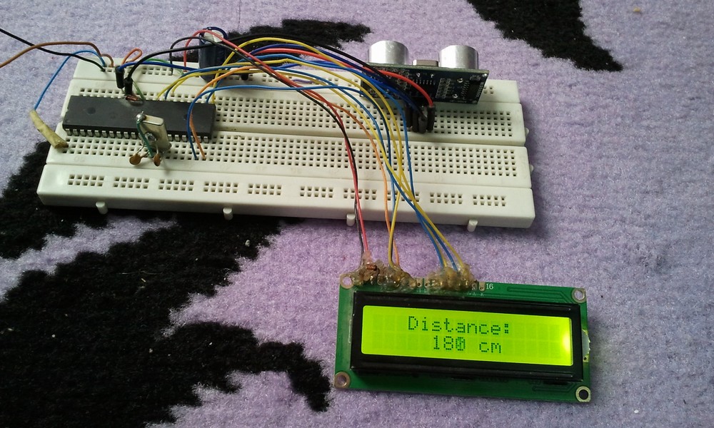
Interfacing PIC16F877A with HC-SR04 ultrasonic sensor video:
The following video shows project prototype circuit.
Discover more from Simple Circuit
Subscribe to get the latest posts sent to your email.

Hello, How is it possible to add a buzzer to this circuit that alarms at a certain distance?
How can i connect this circuit in the proteus simulador?
Could you Please explain the Oscillator frequency calculation? I don’t have a 8mhz crystal and I would like to use a 20mhz. What changes do I need to do?
Why did I install the pcb, it won’t work?
sorry sir, i have problem.
I don’t know why but when i’m using 20MHz crystal or 8Mhz, my simulation didnt work. My lch was just displayed distance and 0cm and change to timeout . Can u have any ideal why i have that problem? Thank you so much for taking your time to help me
you added a header file 16f877a.h. Is it a user defined header file,if that is so what is the code?
That’s the header file the PIC16F877A microcontroller, this file comes with CCS C compiler and it’s not a user defined file!
Could you Please explain the Oscillator frequency calculation? I don’t have a 8mhz crystal and I would like to use a 4mhz. What changes do I need to do?
Timer1_Frequency = MCU_Frequency/(4 x Prescaler)
For MCU_Frequency = 8MHz and Prescaler = 2 (because I used setup_timer_1 (T1_INTERNAL | T1_DIV_BY_2);) we get:
Timer1_Frequency = 8/(4 x 2) = 8/8 = 1MHz
This means Timer1 will increment by 1 every 1 microsecond (1/1MHz = 1 us which is the period).
If the MCU_Frequency = 4MHz and to get Timer1_Frequency = 1MHz:
Prescaler = MCU_Frequency/(4 x Timer1_Frequency) = 4/(4 x 1) = 1.
Timer1 Prescaler = 1 which is available, so use this:
setup_timer_1 (T1_INTERNAL | T1_DIV_BY_1);